


In today’s applications it is increasingly important to use space and resource-saving gears. One possibility is to design the rim of internal gears as thin as possible in order to reduce the overall space as much as possible. This goes along with a significantly greater utilization of the material strength for tooth root fracture,![]() . Instead of wear, micropitting, and pitting, root breakage can happen suddenly without the opportunity to adequately react.
. Instead of wear, micropitting, and pitting, root breakage can happen suddenly without the opportunity to adequately react.
This can lead to breakdowns, or even injuries. Such gears with thin rims need to be analyzed and calculated very accurately to get a reliable assertion of their fatigue resistance for critical applications. This article is meant to analyze the origin, meaning and influence of the thin rim factors ![]() of the AGMA 2001 [4] [5] and
of the AGMA 2001 [4] [5] and![]() , in ISO 6336 [1] [2] and subject them to the calculation of internal gears according to VDI 2737 [3]. The main differences between these methods will be highlighted, using an FEM calculation.
, in ISO 6336 [1] [2] and subject them to the calculation of internal gears according to VDI 2737 [3]. The main differences between these methods will be highlighted, using an FEM calculation.
The Calculation Methods
The AGMA commission established the rim thickness factor ![]() in 1982, based on the paper of Raymond J. Drago [7]. One of the things that was discovered in the various photoelastic and actual strain gauge measurements of this paper is that the AGMA/ISO standard calculations for internal gear tooth bending strength (without considering the rim thickness factor) are quite conservative ([7]). The ratio of measured stress to calculated stress for all external gears is greater than one, while the same ratio for all internal gears is less than 1 (about 0.8 nominally). This is a very consistent ratio for internal gears. (Figure 1)
in 1982, based on the paper of Raymond J. Drago [7]. One of the things that was discovered in the various photoelastic and actual strain gauge measurements of this paper is that the AGMA/ISO standard calculations for internal gear tooth bending strength (without considering the rim thickness factor) are quite conservative ([7]). The ratio of measured stress to calculated stress for all external gears is greater than one, while the same ratio for all internal gears is less than 1 (about 0.8 nominally). This is a very consistent ratio for internal gears. (Figure 1)


The rim thickness factor ![]() is raising the tooth root stress and is weighted the same way as the size factor or the dynamic factor
is raising the tooth root stress and is weighted the same way as the size factor or the dynamic factor![]() . The root stress is calculated from the tangential force Ft as
. The root stress is calculated from the tangential force Ft as
![]()
with the safety associated with the maximum allowed tooth root stress calculated as
![]()
(![]() =Overload factor,
=Overload factor, ![]() =Load distribution factor,
=Load distribution factor, ![]() =Geometry factor,
=Geometry factor, ![]() =Stress cycle factor,
=Stress cycle factor, ![]() =Safety factor,
=Safety factor, ![]() =Allowable bending stress,
=Allowable bending stress, ![]() =Temperature factor,
=Temperature factor, ![]() =Reliability factor).
=Reliability factor).
A calculation of internal gears under consideration of thin rims is not possible with the AGMA 2001, because it is valid for external gears only. The rim factor was adopted in 2006 by the ISO commission with the formula symbol ![]() for the extended calculation of internal gears with thin rims. The tooth root stress is calculated as
for the extended calculation of internal gears with thin rims. The tooth root stress is calculated as
while the safety against tooth root breakage follows from the maximum allowed tooth root stress as
![]()
(![]() =Tooth form factor,
=Tooth form factor, ![]() =Stress correction factor,
=Stress correction factor, ![]() =Helix angle factor,
=Helix angle factor, ![]() =Deep toot form factor,
=Deep toot form factor, ![]() =Application factor,
=Application factor,
![]() =Dynamic factor,
=Dynamic factor, ![]() =Face load factor (root),
=Face load factor (root), ![]() =Transverse coefficient (root)).
=Transverse coefficient (root)).
with 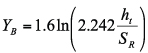 for external gears and
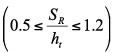
for internal gears 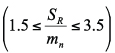

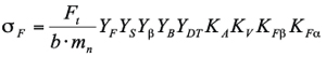
In December 2005 the VDI-guideline 2737 was released, intended for the calculation of internal gears only (Figure 3). It includes two extreme cases: “absolute stiff” and “elastic designed” rims. In the case of the absolute stiff rim the calculated tooth root stress is unaffected by the rim thickness, because the deformation of the rim and the surrounding geometry is not considered. In this case the fatigue safety is quite optimistic. The tooth root stress is calculated as
![]()
(![]() = Tangential force, K = Load factors, Y = Root factors)
= Tangential force, K = Load factors, Y = Root factors)
In the case of the elastic designed rim the free deformation of the rim in its plane is considered, which means that there is no consideration of hindrance of the deformation of the rim through surrounding geometry and mounting. This leads to compression stress in the tooth root because of the normal load, which is amplified through the bending of the rim. Afterwards the rim is rotated by an angle ![]()

(Figure 4) so that the same tooth root experiences tensile stress now. This means that the compression side of tooth root experiences a periodic alternating stress. These two stresses are combined in the double amplitude ![]() .
.
![]() , p = Number of Planets
, p = Number of Planets
The double amplitude is calculated as
![]()
The first component is the resulting local nominal stress ![]() at the compression side of the tooth consisting of the stress contingent
at the compression side of the tooth consisting of the stress contingent ![]() due to the tangential load, the stress
due to the tangential load, the stress ![]() due to radial load, the bending moment
due to radial load, the bending moment ![]() and the stress due to circumferential forces
and the stress due to circumferential forces ![]() :
:
The second component arises due to the bending moment of the rim ![]() and is the largest resulting nominal stress outside of the zone of the tooth contact
and is the largest resulting nominal stress outside of the zone of the tooth contact ![]() :
:
![]()
The fatigue safety can be calculated with ![]() according to DIN 3990, or ISO 6336 as following:
according to DIN 3990, or ISO 6336 as following:

Comparison with FEM
To compare the aforementioned calculation methods and to illustrate their differences, a FEM core was implemented in KISSsoft. A 120° section of an internal gear was developed as a 2D model.
The main differences between the calculation methods become obvious from the model. The calculation approach of ISO 6336 is the consideration of the nominal stress of the loaded tooth. This nominal stress is then adjusted by the ratio of rim thickness and normal module with the factor ![]() ,which considers the influence of rim thickness at the tooth root stress.
,which considers the influence of rim thickness at the tooth root stress.
In contrast, the VDI guideline 2737 is calculating the double amplitude from the compression stress at the compression side of the tooth in contact, and the time shifted tensile stress due to bending of the rim, as described in the previous section. Figure 5

To compare the standards against a FEM-model, it is necessary to consider the boundary conditions of the model. A 2D-model was chosen to reduce the calculation time. The thickness factor ![]() was varied from 0.1 up to 10, which lead to around 11’400 FEM calculations. The boundary condition used for the FEM-model was fixed flanks at the 120° section. Due to this condition the angle
was varied from 0.1 up to 10, which lead to around 11’400 FEM calculations. The boundary condition used for the FEM-model was fixed flanks at the 120° section. Due to this condition the angle ![]() of the FEM-model, compared with the VDI-guideline 2737, is decreased by
of the FEM-model, compared with the VDI-guideline 2737, is decreased by ![]() , but the effect on the double amplitude
, but the effect on the double amplitude ![]() is very small and it is negligible.
is very small and it is negligible.


Figure 6 shows the difference between the “optimistic” calculated tooth root safety according to ISO 6336 and the “pessimistic” calculated tooth root safety according to VDI 2737. Figure 7 shows the bending stress, the compression stress, and the resulting double amplitude. As seen in the graphics these are fitting very well to the stress contingents calculated using FEM and the resulting double amplitude. Note that the VDI 2737 is valid for elastically designed gears, with a thickness factor![]() >1.5, but still it seems that the VDI 2737 gives usable results for smaller values of
>1.5, but still it seems that the VDI 2737 gives usable results for smaller values of ![]()

If we compare the results of the tooth root stress according to ISO 6336 for compression and tensile stress calculated against FEM, shown in Figure 8, we see significant differences. The tensile stress of the tensile side of the tooth is decreasing due to the bending of the rim when the rim factor![]() decreases, and starts to rise drastically when the rim thickness is decreased to 0,5*m. The compression stress, however, fits much better to the stress calculated according to ISO 6336.
decreases, and starts to rise drastically when the rim thickness is decreased to 0,5*m. The compression stress, however, fits much better to the stress calculated according to ISO 6336.
Conclusion
The calculation methods according to ISO 6336, AGMA 2001, and VDI 2737 have their strong and weak points. The ISO 6336, and accordingly AGMA 2001, are relatively easy to handle and provide fast results. In contrast, to understand and use the VDI 2737 a deeper knowledge and understanding about the conditions and the state of stresses of a meshing is necessary. ISO 6336 and VDI 2737 are different in how they consider the influence of the rim thickness, and so the resulting safeties differ as well. While the ISO 6336 considers a stress alternation through the alternation of the rim thickness, the VDI 2737 considers the influence of the bending of the rim itself to the tooth root safety. For the calculation of safety factors through ISO 6336 and VDI 2737 it is necessary to keep in mind that these methods are only valid for their defined conditions (stress concentration, bending of the rim) and should be proofed through the recalculation of existing gearboxes.
References
- International Standard Organization: ISO 6336-1, 2007, Reference number: ISO6336-1:2006(E)
- International Standard Organization: ISO 6336-3, 2007, Reference Number: ISO6336-3:2006(E)
- Verein Deutscher Ingenieure: VDI-Richtlinie 2737 Berechnung der Zahnfußtragfähigkeit von Innenverzahnungen mit Kranzeinfluss, 2005
- American Gear Manufacturers Association: AGMA 2001-D04, 2010, ISBN: 1-55589-839-4
- American Gear Manufacturers Association: AGMA 2101-D04, 2010, ISBN: 1-55589-840-8
- American Gear Manufacturers Association, Raymond J. Drago: A Crane Gear Failure Analysis – Case Study, Observations, Lessons Learned, Recommendations, 2006, ISBN: 1-55589-849-7
- American Gear Manufacturers Association, Raymond J. Drago: An Improvement in the conventional analysis of gear tooth bending fatigue strength, 1982, Paper Number P229.24


