


Printed with permission of the copyright holder, the American Gear Manufacturers Association, 1001 N. Fairfax Street, Suite 500, Alexandria, Virginia 22314. Statements presented in this paper are those of the authors and may not represent the position or opinion of the American Gear Manufacturers Association. (AGMA) This paper was presented October 2017 at the AGMA Fall Technical Meeting in Columbus, Ohio. 17FTM01
Energy efficiency represents one of the most relevant drivers in many application fields, and power transmission and gears play a critical and fundamental role in many of them, contributing to improve the overall efficiency and to reduce energy consumption and emissions.
In the design phase, the availability of tools able to reliably anticipate the losses of a gearbox can provide a relevant contribution to the aim of improving efficiency. The power losses of gearboxes are the sum of different contributions. For some of them, the available analytical models can provide acceptable information but they are not suitable for an accurate prediction of the load-independent losses that are generated by the interaction of the gears with the lubricant.
Computer simulation, in particular the application of Computational Fluid Dynamics (CFD), represents an approach to overcome the problem of predicting load-independent power losses accurately. Moreover, it can provide a description of the lubricant flows inside the gearbox, describing the oil supply to the critical components of the transmission, thus assessing the effectiveness of the lubrication system with respect to reliability.
Nevertheless, the application of CFD to gears is challenging due to the geometrical properties of the volume domain to be studied and its variation during the meshing cycle, with the consequent complexity of the volume mesh handling. Many approaches have been proposed to apply CFD to gearboxes, and they differ in the accuracy of the results and of the simulation time.
This paper, on the basis of a preliminary review of the different approaches, describes the application of CFD to gearboxes based on an original global-remeshing technique, which enables accurate predictions in relatively short simulation times, compatible with the industrial design practice.
The method is validated with data obtained by means of experimental tests, both on laboratory back-to- back test rigs and on industrial gearboxes, including planetary gearboxes, for which the load-independent power losses are particularly relevant.
The results of the CFD simulation are in very good accordance with the tests, both for the amount of the losses and for the flow distribution, and they also provide a tool to understand the origin of the losses, including the effects of churning, windage, pocketing, and cavitation. The results of the practical application used for the validation are included and discussed in the paper.
1: Introduction
The power losses of gearboxes are the sum of different contributions and typically are classified according both to the machine element responsible for their occurrence and their dependency or independency from the transmitted load. For some of them, the available analytical and empirical models can provide acceptable information, but for the load-independent losses of gears, generated by the interaction with the lubricant, these types of models generally do not provide accurate or even acceptable forecasts. Instead, the availability in the design phase of tools able to reliably anticipate the losses of a gearbox, including the load-independent ones, can provide a relevant contribution to the aim of improving efficiency.
Computer simulation, in particular the application of Computational Fluid Dynamics (CFD), represents an approach to overcome the problem of predicting load-independent power losses accurately. Moreover, it can provide a description of the lubricant flows inside the gearbox, describing the oil supply to the critical components of the transmission, thus assessing the effectiveness of the lubrication system with respect to reliability. Nevertheless, the application of CFD to gears is challenging due to the geometrical properties of the volume domain to be studied and its variation during the meshing cycle, with the consequent complexity of the volume mesh handling.
Many approaches have been proposed to apply CFD to gearboxes, and they differ in the accuracy of the results and of the simulation time: a preliminary review of the different approaches has been presented by the authors in [1]. Starting from that, the application of CFD to gearboxes, based on an original global-remeshing technique, which enables accurate predictions in relatively short simulation times, is presented here. The proposed approach represents a good tradeoff between the accuracy of the results and the compatibility with the real industrial design practice in terms of simulation time.
For this reason, the software tools that have been generated represent an effective contribution to the design of gearboxes because they provide, since the preliminary design phases, reliable information concerning the oil supply to critical elements and the power losses. The availability of this information in the early stages of design enables corrective actions that would be costly if applied later, typically when the tests on the first prototypes can be performed.
Concerning the simulation tools, the approach followed by the authors has been implemented utilizing open source codes, which, with a suitable definition of user interfaces and data preprocessing, can be effectively applied to generate computer programs specifically tailored for the application to gears and gearboxes, thus enabling their application by gear designers who are not necessarily experts in the application of CFD simulation by means of general purpose codes.
The method proposed by the authors and the software tools implemented have been validated on the basis of data obtained by means of experimental tests, both on laboratory back-to-back test rigs and on industrial gearboxes, including planetary gearboxes, for which the load-independent power losses are particularly relevant.
The results of the CFD simulation are in very good accordance with the tests, both for the amount of the losses and for the flow distribution.
One other relevant aspect is the possibility to understand the origin of the losses, including the effects of churning, windage, pocketing, and also cavitation, which for some cases represent a way to justify results that would be otherwise difficult to explain. Moreover, a deep understanding of the losses and their dependency from the single effects in each specific application case represents an effective input to address their reduction.
2: Power Losses in Gearboxes
The power dissipation in a gearbox is the combination of the losses generated by different mechanical parts. They can therefore be separated in losses related to gears, to bearings, to seals, and to other components, such as clutches and synchronizers. Moreover, the gear and bearing losses can be subdivided further, according to a second criterion, into load dependent and load-independent losses. The former are directly proportional to the transmitted torque and are associated to the friction between matching parts or, better, in the case of oil lubrication, by the shear actions in the oil film due to sliding. The latter are instead generated by the interaction of the lubricant and the mechanical components.
The classification of the losses is here summarized according to Niemann [2]: identifying the load-independent with the suffix 0, and considering gears (PLG), bearings (PLB), seals (PLS) and other generic losses (PLX) such those of clutches and synchronizers, the total loss can be written as follows
PL = PLG + PLG0 + PLB + PLB0 + PLS0 + PLX [1]
The load-independent power losses of gears, indicated by the symbol PLG0, which are the main objective of this paper, can be subdivided further into churning (PLG0,C), windage (PLG0,W), and squeezing/pocketing losses (PLG0,S).
PLG0 = PLG0,C + PLG0,W + PLG0,S [2]
3: CFD Application to Lubrication of Gearboxes
Windage differs from churning since churning involves the interaction with a fluid mixture (multiple phases), while windage involves a single phase. Churning losses are generally present in all splash-lubricated gearboxes, while windage implies also a significant effect of the interaction with air. Windage can therefore be typical and relevant for large grease-lubricated gears, for which there is no splash and the tangential speeds can be high, or for injection-lubricated high-speed gearboxes which imply a single-phase interaction between the gears and the air. Generally speaking, both phenomena are present in an operating gear transmission. The third source of load-independent losses in gears is squeezing, also named pocketing, which is determined by the rapid variation of the volume between mating teeth when they enter and exit gear mesh, thus producing axial flows of the lubricant or of the lubricant mixtures, responsible for losses generated by viscous effects that, in general, are of a lower order of magnitude when compared with the previously described phenomena.
Load-independent power losses are also present in bearings, and for them, due to a more standard geometry, equations of general application can be defined and used, such as those provided by the manufacturers. Instead, for the gears where the losses are strongly dependent from the specific arrangement and by the boundary conditions determined by the casing geometry, an approach based on analytical/empirical equations of general application does not seem effective, and only numerical methods are appropriate to obtain accurate results.
3.1: Theoretical Background
As a consequence of the previous discussion, the calculation of the load-independent power losses of gears requires the description of the behavior of the lubricant in the operating conditions, which requires the solution of the internal fluid dynamics. An analytical approach to the solution of such a problem is not realistic in the case of gearbox lubrication, due to the complex shape of the domain, which is bounded by the surfaces of the gears, the shafts, and the bearings, which move during the operations. Furthermore, the shape of the casing, which can also be very different from gearbox to gearbox and is typically only partially filled, strongly affects the lubricant fluxes and, therefore, the power losses. The shape of the volume available for the fluid is therefore continuously variable, and the portions occupied by the oil, the air, and the mixture change during the operation. For these reasons, only numerical approaches, i.e. CFD can provide reasonable results. At present, as pointed out in [1], the methods based on particle models are reasonably applicable to calculation aimed at a qualitative description of the flow of lubricant inside the gearbox, while an approach based on finite volumes is required when the numerical evaluation of the losses is the aim. In the present work the numerical solution of the fluid domain inside the gearbox is performed with a finite volume method, which is based on the subdivision of the volume into cells and on the numerical solution of two governing equations, which represent the mass and momentum conservation; in particular:
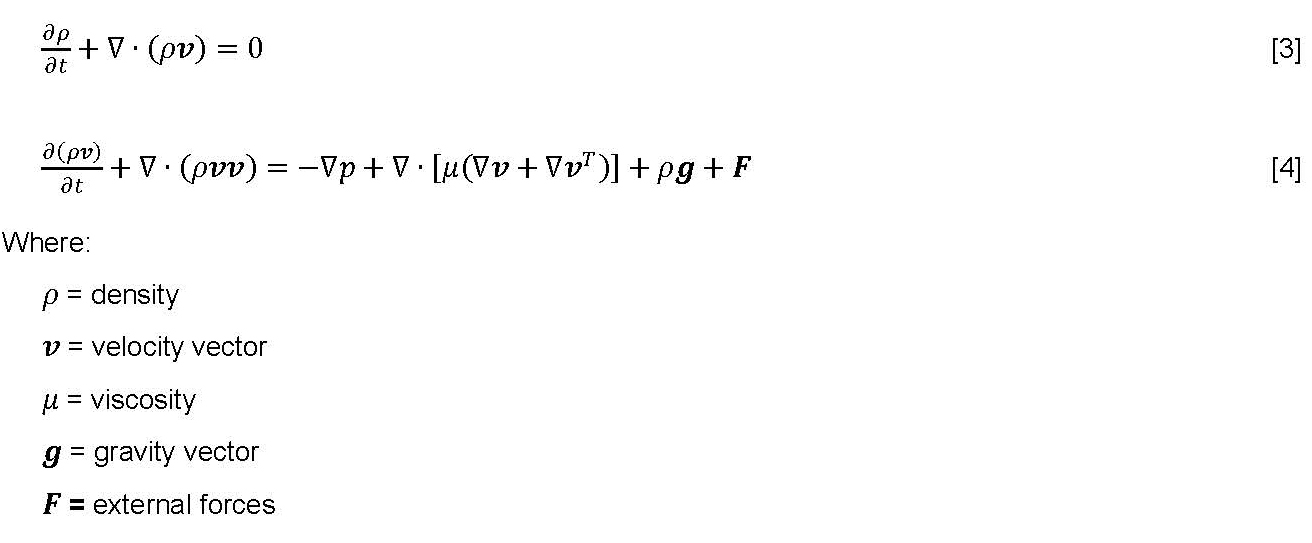 These two equations govern the behavior of a transient incompressible flow and must be enforced in each cell in which the computational domain is discretized.
The numerical approach is based on a solution performed with techniques based on a PIMPLE (merged PISO-SIMPLE) algorithm [4]. Actually, the SIMPLE algorithm has been developed for steady-state conditions and, therefore, even if it is effective does not include the time information. On the other hand, the PISO algorithm, developed for transient simulations, is time conservative, but the convergence of the solution requires the reduction of the time step, thus increasing the computational effort and the necessary time for the completion. The PIMPLE algorithm operates in the SIMPLE mode for all the iterations except the last one, in which it operates in PISO mode. It is therefore possible to combine the results of a stable solution, which does not lose information, with an acceptable computational effort.
The application of splash lubrication, which is characterized by the formation of a mixture of oil/air, requires the introduction of an additional scalar quantity, called volume fraction, used to identify the proportion of the two phases. α is calculated for each cell, with an additional balance equation.
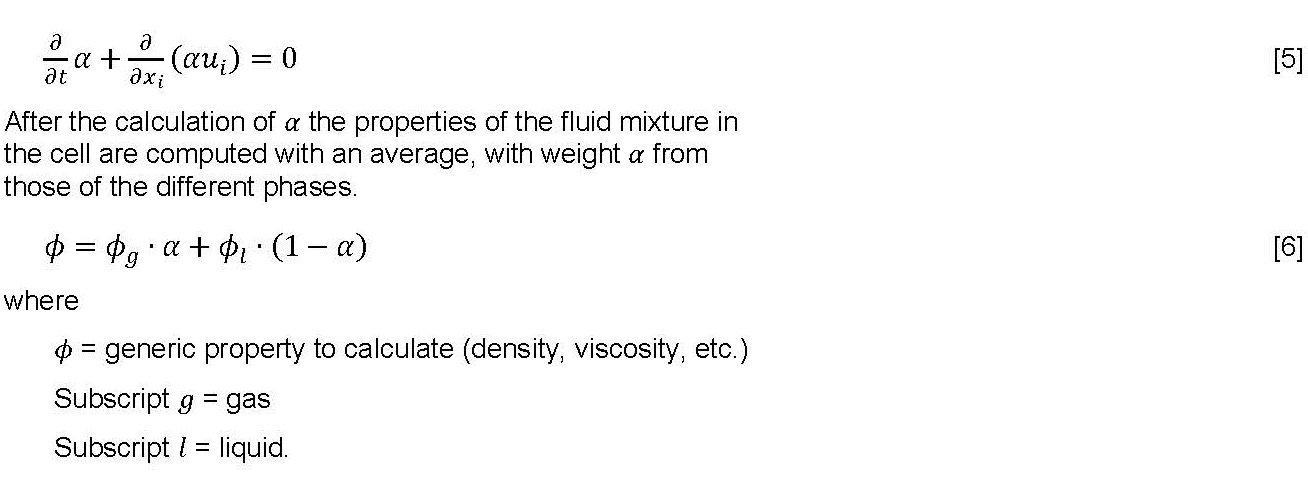 A relatively recent development uses a compressive scheme for the discretization of the gaseous volume fraction α. An artificial supplementary velocity field vc is defined in the proximity of the interface in such a way that the local flow steepens the gradient of the volume fraction function and the interface resolution is improved. A number of different approaches to define the compressive velocity field are reported in literature, e.g. CICSAM (Compressive Interface Capturing Scheme for Arbitrary Meshes) as described by Ubbink [3] and the currently used multi-dimensional universal limiter with explicit solution [4], which limits the flux of the variables to guarantee a bounded solution. More details concerning the techniques used by the authors can be found in [5].
3.2 Mesh Handling
The continuous variation of the geometry of the volume during the operation, determined by the meshing cycles of the gears, gives origin to the major complexity in the simulation of internal fluid dynamics of gearboxes, because it requires an update of the mesh after a few time steps. Actually, the evolution of the volume in the region of teeth meshing gives origin to a severe degeneration of the volume elements, and therefore determines instability of the solution.
The approaches typically adopted by commercial software are not effective for gears. For instance, the most diffused, which is based on a mesh smoothing with a replacement of the elements which do not satisfy the selected criteria, does not represent an acceptable solution because, despite the possibility of handling large topological modifications, in this case they give origin to much smaller elements, thus implying a reduction of the time steps and therefore a growing computational effort.
For this reason, the original solution proposed by the authors is constituted by complete mesh substitutions of the mesh after some iterations. With this approach, which is based on a global-remeshing technique, the regeneration of the grids, being based on predefined topological rules, can be much more controlled with respect to the substitution of the degenerated elements only, the geometry of which is not known in advance. Thus, more homogeneous element size and quality can be ensured. The results are then mapped from the old to the new grid by interpolation. More details are provided about where the approach has been applied to simple cases, such as back-to-back test rigs [6].
The main limitation of the original approach proposed, as described in [7], was the practical limitation to its direct application to cases for which a 2D generation of a mesh and subsequent extrusion is not feasible. For this reason, in order to simulate the lubrication and the power losses of real cases, a new partitioning-based technique has been applied and integrated with the global-remeshing method as described later. The new technique removes the limitations in applicability and opens the possibility of simulating whatever gearbox design, and, in particular, also planetary gears, which represents the application on which the present is mostly focused.
4: Model Validation
Before applying the model to complex cases, for which the different aspects and the different causes of complexity can be present at the same time, the approach has been validated on the basis of experimental data, either referred to simpler geometric condition, or to some single specific aspects. Some steps of the validation process are described.
4.1.1: Back-to-Back Test Rig
In the past the authors have validated the above-mentioned approach by comparing the results in terms of resistant torque due to the interaction with the lubricant and the lubricant distribution on a back-to-back test rig [6]. The experimental part was performed by Otto et al. [8-9]. Tests were performed for different geometries, rotational speeds, filling levels, and pressures. The authors have numerically simulated the above-mentioned configuration, both with general-purposes software based on local-remeshing and with the original global-remeshing approach.
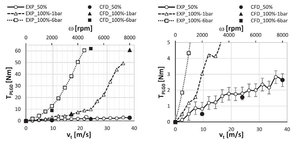
Figure 1 shows a comparison between the experimental results by Otto and the numerical predictions according to the original method presented by the authors.
The three curves represent, for a C-PT gear pair, the power losses as a function of the rotational speed. The dotted line with squares refers to the complete filling of the case and the application of an overpressure of 6bar. The striped line with triangles represent the complete filling of the case without overpressure. The continuous line with circles represents the condition in which the gears are submersed into the lubricant up to the axis. The first curve represents the typical example of windage losses (note: according to the definition, windage means single phase, even if there is oil alone instead of air alone). From a theoretical point of view, also the curve that refers to the non-pressurized condition represents an example of windage. But this is true only as far as the pressure during operation does not decrease up to the vaporization pressure for which the liquid lubricant transforms into vapor. In this case, the proper classification of the losses classification becomes churning. The presence of some vapor regions can also explain the differences between the pressurized and the non-pressurized measurements that, neglecting cavitation, should not be influenced by the static pressure.
The numerical results, besides providing a very accurate prediction of the different kind of losses, can also provide additional information that sometimes cannot be measured experimentally or help in understanding “strange” experimental evidence, providing a physical explanation like in the case of cavitation.

The lower curve, in turn, represents another churning loss condition in which the two phases are the liquid lubricant and the air. Figure 2 shows a comparison between the observed and predicted lubricant distributions. Simulations are capable to capture the main phenomena such as the air trapping below the contact or the oil rivulets leaving the upper teeth.
With the approach based on the use of an open source code with global remeshing, each simulation took about 21h on a single 3.2 GHz CPU (12.8 GFLOPS). The same simulation, using a general-purpose software and a local-remeshing technique, was performed on a 16 CPUs hpc (3.2GHz) (205 GFLOPS): in this case, it took about 20h. Considering a linear scalability, the gain in terms of computational time is 93.5 percent.
4.1.2: Industrial Planetary Gearbox 2D
Another test case used in the past by the authors to validate the results was an industrial planetary gearbox [11]. In such gearing, the load-independent power losses significantly affect the efficiency: the presence of the planet-carrier and the related motion of the planets produce a significant interaction with the lubricant and relevant churning phenomena. Dedicated test and data post processing were performed in order to be able to separate the load-independent power losses of gears from the total losses. Figure 3 shows those results and the comparison with the 2D numerical simulation using the global-remeshing approach.
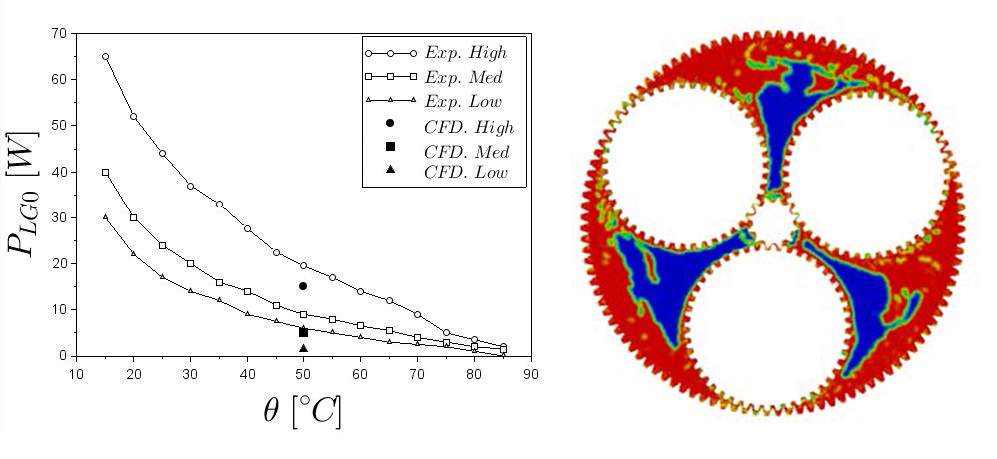
lubricant levels) [11] and lubricant distribution.
The comparison shows that 2D simulations underestimate the load-independent power losses. This can be explained considering Couette’s theory as shown also by other authors [12].
From the above-mentioned examples, it appears on one side that the CFD global-remeshing approach can provide very accurate results in a short manner, and on the other side, it appears clearly that for such kinds of studies, the planar simplification cannot be used for a precise power loss estimation.
4.2: Advanced Mesh Handling Techniques
The most widely diffused technique implemented in commercial software, the so-called local-remeshing, is based on a first mesh smoothing (idealization of the mesh as a network of interconnected springs) and a subsequent local replacement of the elements that quality does not satisfy the selected criteria. This method is effective and is able to manage big topological modifications but is not efficient. The newly generated element results are significantly smaller than the initial ones, imposing a sudden reduction of the time steps (in order to ensure the solution stability), with a significant impact on the computational effort.
The original global-remeshing technique presented by the authors relies on the complete mesh substitution after few iterations and the mapping of the results between the grids. The generation of the new grids can be better controlled than the regeneration of the distorted elements, ensuring a more homogeneous element size and quality.
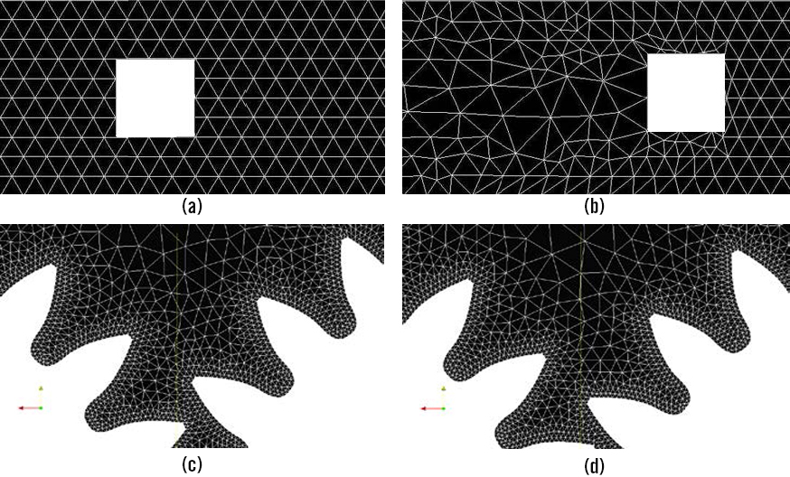
Figure 4 shows how the local-remeshing, also for simple topological modifications, produces very small and/or distorted elements while the new approach is capable to maintain the mesh quality, also for complex geometrical modifications such as mating gears.
In both cases, only a planar 2-dimensional tetrahedral mesh is newly generated. This planar grid is successively extruded. This is the limiting factor that prevents the direct application of such a method to complex gearbox configurations.
The simulation of the back-to-back test rig result is possibly taking advantage of the plane of symmetry. The computational domain was subsequently partitioned axially into two sub-domains. The mid-plane was meshed following a top down strategy that starts by computing the corner points, and discretize the edges and the faces with an advancing front surface mesh generator. A fast Delaunay algorithm generates the mesh. Eventually it fails for the last elements, and a back-tracking rule-base algorithm takes over [13, 14]. The initial planar mesh with three internal partitions (corresponding to the lateral surfaces of the gears and the remaining area that surrounds the gears) was extruded in the two directions so as to create the final grid (the partitions corresponding to the gear flanks are extruded just in one direction while the remaining partition in both directions).
The planetary gearbox was instead simulated with a 2D approximation: The complex geometry, the presence of the planet carrier etc., does not allow the direct application of such kind of methodology.
For this reason, considering the importance of simulating the lubrication and the power dissipation of real gearboxes, the authors integrate a new and innovative partitioning-based meshing technique to the already presented global-remeshing method so as to be able to apply such extrusion strategy to each possible gearbox design. In particular, the same gearbox considered in the previous research was simulated, overcoming the 2D simplification.
5: Simulation of a 3D Planetary Gearbox
The most recent developments are represented by the application of the global-remeshing approach to a 3D planetary gearbox.
5.1: Model Description
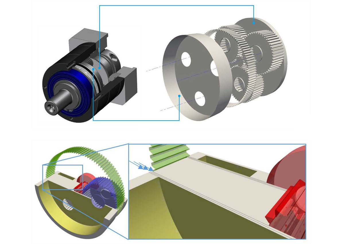
The gearbox considered is a single stage planetary gearbox with a reduction ratio of 10. The detailed geometrical properties are reported in Table 1.
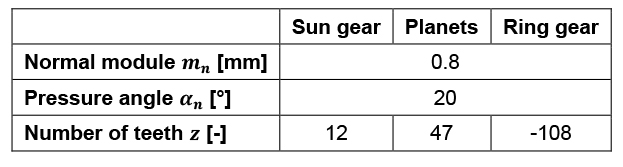
In order to be able to apply the previously described global-remeshing strategy to the three-dimensional case, the computational domain needs to be subdivided into slices in an axial direction with a technique that can be defined as axial partitioning: Figure 5 shows the seven axial partitions used for the present case. Each partition is discretized with an extruded mesh. The procedure relies on an automatized algorithm that, for a prescribed time step, generates the planar geometries for each partition. These are then discretized and the resulting grid extruded. Each sector (partition) of the global grid is generated and meshed separately and can be handled by a different cpu so as to speed up the meshing procedure. As a consequence of this, while the geometries at the interfaces are conformal, the meshes are not. Through the introduction of an arbitrary mesh interface (AMI), the different partitions (disconnected from a geometrical point of view) result numerically connected. This ensures that during the simulations, the field variables remain the same at both sides of the interfaces.
AMI for non-conformal patches has been implemented based on the algorithm described in Farrel et al. [15]. AMI is a technique that allows simulation across disconnected, but adjacent, mesh domains. The domains can be stationary or move relative to one another.
The simulation tool was implemented in the OpenFOAM® environment [16]. The fluid dynamic solver was already available. Instead, the algorithm for the boundary motion, for the automation of the mesh generation and updating, as well as for the assembly of the different partitions, was developed on purpose. As described in detail in [7], before each time step, all the dictionaries that control the simulation were automatically modified. The fluid dynamic is solved upon a prescribed time for which the mesh reaches the maximum acceptable distortion.
5.2: Results and Discussion
Figure 6 shows the evolution of the lubricant distribution. Besides the acceleration of the fluids due to the roto-translation of the planets, Taylor-Couette flows arise between the rotating sides of the planet carrier and counter plate and the fixed and planar internal surfaces of the housing. It is evident that these effects can be captured only with three-dimensional simulations.
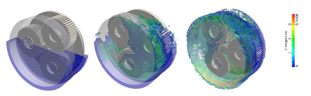
The pure lubricant is pushed in the region the teeth of the ring gear due to the centrifugal effects caused by the rotation of the planets that induces a main circulation also in the lubricant. The air is mainly confined near the axis of the gearbox. In the region between them, there is instead the generation of a lubricant foam (air-lubricant mixture). This foam is also present in the gaps between the teeth as shown experimentally by Chernoray [17].
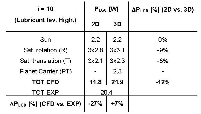
The simulation has been performed for different levels of the lubricant: Table 2 shows, for one of the levels (high), respectively the differences between the experimental tests and the simulation and between the 2D and 3D simulation. From the comparisons it appears that the 3D approach gives results much more in agreement with the experimental evidence.

Figure 7 shows clearly that when the teeth are meshing, the foam condensates, ensuring the separation of the flanks through the formation of a lubricant layer. This is fundamental to reduce the friction coefficient as well as to prevent damaging determined by the contact between metals, like wear and scuffing.
The final 3D mesh consists in approximately 1M cells. The simulation was performed on a 16 3.3GHz CPUs hpc (211 GFLOPS). The 3D simulation took about 30 h to reach the regime condition. The share of the computational effort between the different steps of the simulation can be evaluated as approximately 5 percent for the geometry generation, 10 percent for the mesh generation, 10 percent for the mapping of the fields from the old to the new meshes, and 75 percent for the solution of the internal fluid dynamics.
Considering the perfect scalability, by using 256 CPUs, the calculation time can be reduced to less than 2h resulting in alignment with industrial practice.
6: Conclusions
In the context of a growing interest and focus on the energy efficiency and reliability of the gearboxes, CFD has proven to be an effective approach to calculate the load-independent power losses, for which there are no accurate and/or reliable analytical/empiric formulations, and for the study of lubricant flows and supply to the mechanical component of the transmission.
Starting from analysis which proves that the presently commercially available tools are not directly applicable to real gearboxes, mainly due to the limited effectiveness of the mesh handling technique adopted, the authors have proposed and applied an approach based on the use of an open source code, in order to provide gear designer of an effective tool. The method proposed is based on finite volume element, for which the equations of fluid dynamics are solved numerically on the basis of a global-remeshing technique.
The method has been validated on the basis of simple preliminary applications, for which test data were available, for instance test rigs. During the validation, additional effects that traditionally are not considered have also been taken into account, for instance cavitation. The validation process has shown not only the good reliability of the results in terms of losses and flows, but also the possibility of better understanding the physical phenomena involved, thus providing a key to discuss the results and to properly address the design improvements.
The method, after an additional phase devoted to the define a more developed version of the global remeshing approach, suitable for the application to real gearboxes, has been utilized to analyze the most complete case, corresponding to a planetary gearbox, which has been simulated by means of 3D models.
The results have proven that accurate and reliable results can be obtained in times which are compatible with the practices of a real company context. The tool simulated represents therefore an effective tool to improve, since the preliminary phases of the design process, the efficiency of a gearbox and the effectiveness of the lubrication system.
The developments under course are aimed at improving the user interfaces, so as to enlarge the basis of potential application in design offices.
References
- Concli, F., Gorla, C., 2016, “Windage, Churning and Pocketing Power Losses of Gears: Different Modeling Approaches for different Goals,” Forschung im Ingenieurwesen/Engineering Research, 80(3-4), pp 85–99.
- Niemann, G., Winter, H., 2002, Maschinenelemente Band 2: Getriebe allgemein, Zahnradgetriebe – Grundlagen, Stirnradgetriebe, Springer Verlag.
- Ubbink O., 1997, Numerical prediction of the two fluid systems with sharp interfaces, Ph.D. Thesis, University of London
- Rusche H., 2002, Computational fluid dynamics of dispersed two-phase flows at high phase fractions, Ph.D. Thesis, Department of Mechanical Engineering, Imperial College of Science, Technology & Medicine, London
- Concli F., Gorla C., 2016, “Numerical modeling of the power losses in geared transmissions: Windage, churning and cavitation simulations with a new integrated approach that drastically reduces the computational effort,” Tribology International, 103, pp. 58–68
- Concli, F., Gorla, C., Stahl, K., Höhn, B.-R., Michaelis, K., Schultheiß, H., Stemplinger, J.-P., 2013 “Load independent power losses of ordinary gears: Numerical and experimental analysis,” 5th World Tribology Congress, WTC 2013(2), pp. 1243–1246.
- Concli, F., Della Torre, A., Gorla, C., Montenegro, G., 2016, “A New Integrated Approach for the Prediction of the Load Independent Power Losses of Gears: Development of a Mesh-Handling Algorithm to Reduce the CFD Simulation Time,” Advances in Tribology, 2957151, DOI: 10.1155/2016/2957151
- B.R. Hohn, K. Michaelis, and H. P. Otto, “Influence on noload gear losses,” in Proceedings of the Ecotrib Conference, 2, pp. 639–644, 2011.
- Otto, H.-P.: Flank load carrying capacity and power loss reduction by minimised lubrication, Diss. TU München, 2009
- Andersson M.Churning losses and efficiency in gearboxes [Dissertation]. Stockholm: Royal Institute of Technology; 2014.
- Concli F., Gorla C., 2017, “Numerical modeling of the churning power losses in planetary gearboxes: An innovative partitioning‐based meshing methodology for the application of a computational effort reduction strategy to complex gearbox configurations,” Lubrication Science, DOI: 10.1002/ls.1380
- Durans de Gevigney J., Changenet C., Ville F., Velex P., Becquerelle S., 2013, “Experimental investigation on the no-load dependent power losses in planetary gear set,” International Conference on Gears 2013, 219(2), VDI
- Netgen. www.hpfem.jku.at/netgen/
- Schöberl J., 1997, An advancing front 2D/3D-mesh generator based on abstract rules, Computing
and Visualization in Science, Springer - Farrell P. E., Maddison J. R., Conservative interpolation between volume meshes by local galerkin
projection, Comput. Methods Appl. Mech. Eng. 200, 89–100 (2011) - OpenFOAM. http://www.openfoam.com
- Chernoray V., Jahanmiri M., 2011, Experimental study of multiphase flow in a model gearbox, WIT Transactions on Engineering Sciences 70, 153–164
About the authors Franco Concli is with the Free University of Bolzano/Bozen. Carlo Gorla is with the Politecnico di Milano. Copyright © 2017 American Gear Manufacturers Association (AGMA) ISBN: 978-1-55589-527-3. The statements and opinions contained herein are those of the author and should not be construed as an official action or opinion of the AGMA.


