


Gashing in gear milling applications is basically a slotting operation. Whether it is a gear tool such as a CoroMill® 170 or a standard slotting cutter such as the CoroMill® 331, the aim is to apply the correct feed rate to take advantage of chip thinning. When a programmer or operator fails to take chip thinning into consideration, there will be a loss of productivity and tool performance.
Therefore, it is important to apply the same chip-thinning principals that we use in slot milling, with the appropriate formulas and calculations, to squeeze every last drop of productivity out of many gear milling operations.
Every Last Drop
Gashing or disk milling internal and external gear teeth can be an economical and productive way to approach gears. One way to optimize productivity in gashing is to understand the basics of chip thinning.
Manufacturers give two feed recommendations: fz, which is the programmed feed, or hex, which is the maximum chip thickness. When a cutter is set to a radial engagement of cut equal or greater than its radius, feed per tooth ( fz) and maximum chip thickness (hex) will be equal to each other. However, when the radial engagement is less than the radius, chip thinning occurs (Figure 1). The second condition is always the case in gashing operations due to the relatively small radial engagement of a gear tooth compared to the cutter diameter.

Feed per tooth – fz is a basic value for calculating the machine’s programmed feed rate. It must calculated to optimize operations with respect to maximum chip thickness, or hex. This value is a result of the cutter engagement as it is related to cutter diameter.
When conventional slotting with a CoroMill® 331 using a 250mm (10.0”) diameter, for instance, you could have multiple depths of cut. This can lead to lots of variables in chip thinning equations. But in gear milling, each cut is a known value, because you’re cutting a tooth size that has a constant depth. With a 250mm (10.0”) gashing disk for a module 12 (DP 2.1) gear tooth, we can use a constant multiplication factor. Therefore, a reference chart can be used based on the module (tooth) size, the cutter diameter and the multiplication factor.
In the example above, the tooth depth will be roughly 27mm (1.063”) when using a dedendum (hf) of 1.25*mn. This value can change slightly depending on the operation. Roughing cutters such as a CoroMill® 170 would leave some finishing stock on the root diameter. Therefore, the multiplier could be slightly less. A finishing or semi-finishing tool would cut the tool to full depth. In addition, this value can change based on end user design requirements. A common cutter diameter for this size tooth would be 200 to 300mm (8 to 12”). By having such a small radial engagement compared to the cutter diameter, there’s a relatively large amount of chip thinning – a factor of 1.46 to 1.75 or a 46 to 75% increase. Use the table below to calculate fz based on the cutter diameter, module size and the proper hex value for the insert. (Table 1)

The chip thickness is an important consideration when deciding the feed per tooth, to ensure that the most productive table feed is employed. The hex is used to calculate the fz in the chip thinning formula.
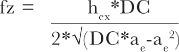
Where, DC = cutting diameter
And ae = radial engagement
Example 250mm diameter module 12 cutter running at hex of 0.3mm (.012”)
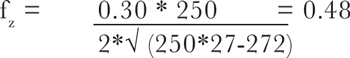
Using the chart fz = 0.30 *1.61 = 0.48
Ignoring this chip thinning formula, there is a chance that the feed rate will be too low for the insert geometry or edge preparation. The general rule in milling is to avoid going below .076mm or .003” hex as there will also be some tolerance on the position / run-out in the tool body. Too low a hex value can result in more of a rubbing effect than actual cutting, generating additional heat in the process. This inevitably creates a loss in tool life and productivity. Maximum chip thickness (hex) recommendations can be found in the manufacturers’ catalogs or on their website.
In finishing operations, the scallop height on the flank or root will restrict the feed rate to achieve the desired finish. The chip thinning compensation should still be used to achieve the highest productivity then adjusted for the correct surface finish.
While there is chip thinning due to the radial engagement, there is also chip thinning as a result of the lead (entering) angle of the tool. However, the compensation is typically built into the cutter design instead of the feed rate. Most manufacturers will use half to a third as many effective flank inserts as the number of effective root inserts. As an example, a 350mm diameter CoroMill® 170 roughing cutter has 8 effective root inserts, with 2 sets of 4 effective flank inserts to achieve the full depth (Figure 2). This means the flank insert with have twice the feed rate (fz) of the root inserts. This is needed to compensate for the 20° angle of the tool.


Using this tool: 8 effective root inserts running with a fz value of 0.53mm (.021”) and hex of 0.30mm (.012”). The flank inserts will have a fz of 1.06mm per insert. Using the SIN of 20 degrees (.342), which is the pressure angle of the tool, the 4 effective flank inserts will have a hex value of 1.06 * .342 / 1.75 = .21mm (.008”). The 1.75 in the calculation is for the radial chip thinning and can be found in the table for a Module 12 350mm cutter.
In the end, it is about maximizing the output of gear milling. Without taking into consideration chip thinning in gashing operations, especially roughing, there will a risk of lost productivity and poor tool performance.


