


Abstract
This paper is aimed at the development of a novel design of precision gear hob for the machining of involute gears on a conventional gear-hobbing machine. The reported research is based on the use of fundamental results obtained in analytical mechanics of gearing. For solving the problem, both the descriptive-geometry-based methods (further DGB-methods) together with pure analytical methods have been employed. The use of DGB-methods is insightful for solving most of the principal problems, which consequently have an analytical solution. These analytical methods provide an example of the application of the DG/K-method of surface generation earlier developed by the author. For interpretation of the results of research, several computer codes in the commercial software MathCAD/Scientific were composed. Ultimately, a method of computation of parameters of design of a hob with straight-line lateral cutting edges for the machining of precision involute gears is developed in the paper. The coincidence of the straight-line lateral cutting edges of the hob with the straight-line characteristics of its generating surface eliminates the major source of deviations of the hobbed involute gears. The relationship between major principal design parameters that affect the gear hob performance are investigated with use of vector algebra, matrix calculus, and elements of differential geometry. Gear hobs of the proposed design yield elimination of the principal and major source of deviation of the desired hob tooth profile from the actual hob tooth profile. The reported results of research are ready to put in practice. This is the conclusion of a two-part series. Part I can be downloaded at www.gearsolutions.com
 Introduction
The pitch diameter neither of the new hob, nor of the completely worn hob, could be used for the computation of parameters of design of the gear hob. For accurate computations it is recommended to use pitch diameter of the partly worn gear hob that correlates with outside diameter of the cutting tool. Outside diameter of the new gear hob is equal to do.h (Figure 10), while outside diameter of the completely worn gear hob could be computed from the equation (do.h − Δdoo.h ). For computation of the outside diameter reduction Δ doo.h , the following approximate equation
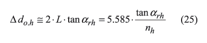
is derived. Here it is designated that: L is a distance between two neighboring hob teeth that is measured along the helix on the outside cylinder of the hob (Figure 10), αrh is clearance angle at the top cutting edge of the hob tooth, and nh is effective number of the hob teeth.

For involute hobs with straight slots, nh is always an integer number, and it is always equal to the actual hob teeth number n(a)h which is usually in the range of nn(a)h = 8∼16 [because of this, the distance L can be computed from equation ∪L=(π⋅do.h)/nn(a)h ].
For gear hobs with helical slots, the effective hob teeth number nh is always a number with fractions. Moreover, the actual value of nh depends upon the hand of helix of slots. This is due to that in the last case the distance L is computed from the equation ∪L=(π⋅do.h)/nn(a)h ]+Px.h ⋅Nh ⋅ cos λrf ⋅ sin λrf [1], [13], [14] and others. Here is designated: d o.h is outside diameter of the hob, Px.h is axial pitch of the hob, Nh is the hob starts number, λrf is lead angle of the hob rake face λrf is the signed value).
Equation (25) is a simple one. It is an approximation, which returns reasonably accurate results of computation.
The performed analysis of the gear hob design reveals that decrease of number of starts Nh of the hob (Figure 11) (a), increase of normal pressure angle φn (Figure 12) (b), increase of the hob-setting angle ζh (Figure 13) (c), and increase of the hob pitch diameter dh (Figure 11 through Figure 13) (d) result in reduction of the angle ξ of the rake surface orientation.


ξ ( m = 10 mm, 20 deg φn = 20 deg, Ng = 1, nh =10, αt = 12 deg ).
The plots (Figure 11 through Figure 13) are created using commercial software MathCAD/Scientific. Unfortunately, the lack of capabilities of MathCAD/Scientific imposed restrictions on graphical interpretation of the functions ξ = ξ (Nh) , ξ =ξ(φn)n, ξ =ξ(ζh), and ξ = ξ (dh). The lack of capabilities is the sole reason that the listed functions are interpreted as a function ξ = ξ (dh) under various values of the gear hob number starts Nh (Figure 11), normal pressure angle φn (Figure 12), and the gear hob-setting angle (Figure 11 through Figure 13). However, Figure 13 provide clear understanding of the impact of the above mentioned parameters of the gear hob design onto the rake face inclination (ξ).
It is important to single out here that the hob pitch diameter could be significantly increased due to the application of hobs with internal location of teeth, the use of which allows hobbing of numerous gears either in one set-up or simultaneously.
Internal hobbing could be performed with the application of a gear hobbing machine of special design [13].
One could suppose that in the ideal case, the equality ξ = −ψh has to be observed. Actually, this equality is not of importance for the design of finishing, as well as of semi-finishing precision involute hob. Finishing and semi-finishing gear hobs cut thin chips, the thickness of which is comparable with the hob cutting edge roundness ρh . Therefore, not the rake angle but the cutting edge roundness directly affects the chip removal process in hobbing of precision involute gears.
For precision gear finishing hobs of big modulus m, for example for semi-finishing and finishing skiving hobs, the top cutting edges are out of contact since the gear bottom land is completely machined on a gear roughing operation [8], [18].
Therefore, the geometry of the top cutting edge is out of importance for the finishing and semi-finishing precision gear hobs of the developed design.
The geometry of the active part of the cutting teeth of the involute hob is a subject of another paper to be submitted. Investigation of this problem is of importance, firstly because the rake face is not orthogonal to the generating surface T of an involute hob.
An approximation of the rake surface of the gear hob could be feasible. In the event of approximation of the rake surface, the rake surface could be shaped in the form of a screw surface of that same hand as the hand of the screw involute surface of the generating surface T of the gear hob. Helix angle of the screw rake surface is equal to ψrf = 90°−ξ.
Either the rake surfaces or the clearance surfaces of the worn gear hob could be reground. A novel technology of the hob regrinding operation has been developed. A comprehensive analysis of the gear hob regrinding operation is a topic to be reported in another paper.
4. Hob Design Extension
Here we consider a precision hob for machining of a modified involute gear as an extension of the original design of a gear hob. The reported results of analysis of inclination of the rake surface of the involute hob teeth (see Section 3) uncovered an opportunity of hobbing of modified involute gear (Figure 14).

The straight-line lateral cutting edges of the gear hob align with the straight-line characteristic Eh of the hob. Searching for an opportunity of reduction of the rake face inclination (i.e. reduction of ξ ), one could turn his/her attention to a possibility of turning of the characteristic Eh (and the gear hob cutting edge as well) through a certain angle Φ about a point K on the pitch line of the auxiliary rack R of the gear hob. The rotation of Eh definitely reduces the rake-face inclination ξ . However, at that same time the rotation of Eh results in curved lateral profile of the auxiliary rack Rm tooth5. The last gives a possibility of hobbing of modified involute gear. For this purposes a gear hob of novel design is developed [17].
The required angle Φ can be computed from the Euler’s formula

Here, the principal radii of curvature R1.T and R2.T of the modified auxiliary rack surface Rm are equal to [1] [19]

Finally, one could come up with an equation

for computation of the necessary value of the angle Φ .
A possibility of modification of the gear tooth profile could easily be illustrated by the characteristic curves of novel kind recently developed by the author [20], say by the AnR(T) -indicatrix of the first kind, and the Ank(T) -indicatrix of the second kind.
The AnR(T) -indicatrix of the first kind could be given in matrix representation

This characteristic curve illustrates the distribution of normal radii of curvature RT(Φ) of the surface T in differential vicinity of K (Figure 15).

(DIN 8002A, Cat.-No 2022, Ident. No 1202055).
The Ank(T) -indicatrix of the second kind could also be given in matrix representation

This characteristic curve illustrates the distribution of normal curvature kT(Φ) of the surface T in differential vicinity of K (Figure 15).
Figure 15 describes that the gear hob of the proposed design [17] enables any desirable value of the involute gear tooth modification (RT).
Both the characteristic curves AnR(T) and Ank(T) are derived using a generalized equation for the Plücker’s conoid [21], [22].
The possibility of the involute gear tooth profile modification can also be proven in another way. For this purpose it is convenient to represent the well known equation for RT=Φ 1.TΦ 2.T in exploded form. Then, the expressions for RT(Φ) and for kT(Φ) could be replaced with the similar expressions RT (υ) and kT(υ) in terms of υ

Here is designated υ = dVT/dUT.
The extreme values R1.T and R2.T , as well as k1.T and k2.T occur at roots υ1 and υ2 of

Here, Eh , Fh and Gh designate Gaussian coefficients of the first fundamental form Φ1.T of the machining surface T of the involute hob. They are functions of the Uh − and Vh − parameters [see Eq. (12)], i.e. Eh=Eh(Uh,Vh), Fh=Fh(Uh,Vh) and Gh=Gh(Uh,Vh). The coefficients Eh , Fh and Gh are derived from Eq. (12) using for this purpose equations:
 Gaussian coefficients of the second fundamental form Φ 2.T of the machining surface T of the involute hob are designated as Lh , Mh and Nh. They also are functions of the Uh− and Vh− parameters [see Eq. (12)], i.e. Lh=Lh(Uh,Vh), Mh=Mh(Uh,Vh) and Nh=Eh(Uh,Vh). The coefficients Lh , Mh and Nh are derived from Eq. (12) using for this purpose equations:

Both the characteristic curves RT=RT(υ) and kT=kT(υ) (Figure 16) perfectly correlate with the AnR(T) – indicatrix of the first kind and the Ank(T) -indicatrix of the second kind of the surface T [1].

Computation of parameters of design of the gear hob with modified tooth profile is almost identical to computation of parameters of design of the gear hob with non-modified tooth profile. The difference is just in computation of the parameter Rm and the distance dm . The parameter Rm differs from the parameter R [see Eq. (13)], and the distance dm is not equal to the gear hob base diameter db.h .
Actual value of R is required to be expressed in terms of the gear hob tooth modification RT . For this purpose, it is convenient to solve an elementary geometrical problem, say to determine coordinates of a certain point S of intersection of the circular arc of the radius RT (Figure 14) with the centerline of the modified tooth profile. The point S is not shown in Figure 14 . Then, the parameter Rm can be determined as a distance of the point S from the gear hob axis of rotation Oh. Following the described routine, one could come with the equation for Rm
 The corresponding equation for the distance dm could be represented in the form
 where
where

The modification of the gear hob tooth profile requires in transition from the generating surface T to another generating surface Tm , i.e. in transition from the T to the Tm . However, the angles φn and ζh don’t change their value, and remain of the same value as for the initial machining surface T. This occurs similarly with a one-sheet hyperboloid of revolution having hyperbolic axial section, besides the surface could be generated by a straight line.
Involute gear hob of the proposed design [17] also features straight lateral cutting edges by means of which it provides hyperbolic modification of the gear tooth profile.
The hyperbolic modification enhances known kinds of modification of the gear tooth profile, say of (a) circular modification, (b) parabolic modification, (c) topological modification etc [9], [23]. The interested reader may wish to go to the appendix for details on computation of the design parameters of the involute hob with the modified tooth profile.
The reported results of the research could be enhanced to hobbing of cylindrical gears with curvilinear shaped teeth [24], to hobbing of spiral bevel gears with modified tooth profile [25], etc. In conclusion, a novel design of a precision involute gear hob is proposed in the paper. The results of this research are ready to be put into practice.
Acknowledgement
It is a pleasure to thank the anonymous referees of this paper for their careful reading of the original manuscript and their valuable comments.
Appendix
The following is an example of the computation of parameters of design of the precision involute hob having a modified tooth profile: Consider an involute hob having major design parameters like FETTE involute hob (Ident. No 1202055) has.
The modified tooth profile is a hyperbola through three points a3 , ak and a4. The desired hyperbolic tooth profile is approximated with a circular arc through the same three points a3 , ak and a4. It is assumed that the approximation doesn’t affect the accuracy of the finishing gear hobbing.
The initial hob tooth profile is not modified. It is a straight line through the points a1(x1,y1), ak(xk,yk) and a2(x2,y2) (Figure A1). Actually, for the involute hob Ident. No 1202055, one can compute coordinates x1= 0mm , y1 = 0mm, xk = 3.64mm, yk =10mm and x2 = 8.189mm , y2 = 22.5mm.

The hob tooth profile has modification of 0.127 mm. Therefore, x3 = −0.127mm , y3 = 0mm and x4 = 8.062mm , y4 = 22.5mm.
In order to provide the involute hob tooth modification of that range, the tooth profile radius of curvature RT is necessary to be equal to

where

The first principal radius of curvature R1.T of the generating surface T of the hob [Eq. (27)]
 The required value of angle Φ[Eq. (28)]

The angle ν * (Figure A2) that projection of the lateral cutting edge onto XhYh coordinate plane makes with the centerline is of the value of ν* = 3.835deg.

d*b h and R* of the precision involute hob having modified tooth profile.
The above computed design parameters of the precision involute hob yield computation of R* = 123.175mm and d*b.h = 16.478mm . These values are obtained on solution of triangles (Figure A2).
Finally, Eq. (23) yields for ξm

For computation of Φ*r

Eq. (24) has been used. This is the conclusion of a two-part series. Part I can be downloaded at www.gearsolutions.com.
References
19. Radzevich, S.P., Goodman, E.D., Palaguta, V.A., “Tooth Surface Fundamental Forms in Gear Technology,” University of Niš, the Scientific Journal Facta Universitatis, Series: Mechanical Engineering, Vol. 1, No. 5, 1998, pp. 515-525.
20. Radzevich, S.P., “A Possibility of Application of Plücker’s Conoid for Mathematical Modeling of Contact of Two Smooth Regular Surfaces in the First Order of Tangency,” Mathematical and Computer Modeling, Vol.42, Issues 9-10, November, 2005, pp.999-1022.
21. Plücker, J., “On a New Geometry of Space,” Philosophical Transactions of the Royal Society of London, Vol. 155, 1865, pp.725-791.
22. Radzevich, S.P., “Mathematical Modeling of Contact of Two Surfaces in the First Order of Tangency,” Mathematical and Computer Modeling; May 2004, Vol.39, Issue 9-10, pp.1083-1112.
23. Radzevich, S.P., “Computation of Parameters of a Form Grinding Wheel for Grinding of Shaving Cutter for Plunge Shaving of Topologically Modified Involute Pinion,” ASME J. of Manufacturing Science and Engineering, November, 2005, Vol. 127, Issue 4, pp. 819-828.
24. Tseng, J.-T., Tsay, C.-B., “Mathematical Modeling and Surface Deviation of Cylindrical Gears with Curvilinear Shaped Teeth Cut by a Hob Cutter,” ASME J Mechanical Design, September 2005, Vol. 127, Issue 5, pp.982-987.
25. Wang, P.-Y., Fong, Z.-H., “Fourth-Order Kinematic Synthesis for Face-Milling Spiral Bevel Gears with Modified Radial Motion (MRM) Correction,” ASME J Mechanical Design, March 2006, Vol. 128, Issue 2, pp.457-467.
Foot Notes
5) In order to clarify the transition from the auxiliary rack R with straight-line tooth profile to the auxiliary rack Rm with curved tooth profile, it is convenient to consider the following analogy. When a straight line is rotating about an axis that is parallel to the line, a surface of circular cylinder is generated. Then consider the straight line that is inclined to the axis of rotation. Consecutive positions of the straight line form a surface of a single-sheet hyperboloid of revolution.
6) Descriptive-geometry-based methods serve as prefect “filter” for detection and elimination of rough errors of the analysis.


