


The continuing retirement of “old hands” in the heat treatment industry has a growing generation of operators, supervisors, and engineers not knowing the severe danger that the presence of water can have on quenching. A recent spate of fires at heat treating facilities due to water in the quench oil has convinced me that it is time for a primer on the dangers of water in quench oil.
Water in quench oil is to be avoided at all costs. Part distortion and cracking can occur with low levels of water in quench oil. High levels of water in quench oil can cause fires and explosions, along with the resulting equipment destruction and downtime. It is not unheard of that, after a major fire from water, a heat-treating shop never opens again.
Water in quench oil can be roughly divided into two different forms based on the concentration of water: water less than saturation and water greater than saturation, where free water exists in the quench tank. The effect of water differs based on the quantity of water present. As a rule of thumb, the saturation point of most conventional quench oils is on the order of 1,000 ppm (0.1 percent).
When the water content of the oil is less than the saturation point, the oil exists as small droplets mixed with the oil. It can also exist as a light emulsification. When the water content is less than the saturation point, it can have some significant effects on the microstructure and distortion of heat-treated parts. The cooling curve of oils containing minute quantities of water show very distinct characteristics:
- Increased stability of the vapor phase.
- Increase length of the vapor phase.
- Increase rate of nucleate boiling.
- Decreased transition temperature between nucleate boiling and convection.
- In extreme cases, the transition between nucleate boiling and convection can be completely suppressed.
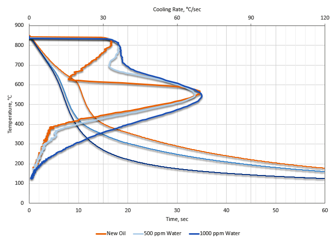
These changes in the cooling curve behavior of cold quench oil can be observed in Figure 1. It can be observed that the vapor phase becomes significantly more stable, and the maximum cooling rates increase. Also the temperature at maximum temperature decreases as the water content is increased. At extreme water concentrations, the convection phase disappears. All of these things increase the potential for distortion and quench cracking. If there are regions of localized stable vapor phase, then soft spots could also occur.
The presence of low levels of water (less than 500 ppm) can result in soft spots, and non-martensitic transformation products in low hardenability steels. It can also result in cracking and increased distortion. At water levels exceeding 1,000 ppm (0.1 percent), a severe risk of fire and explosion exists due to the conversion of water to steam and the subsequent expansion. This is especially true of integral quench atmosphere furnaces.
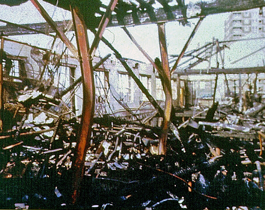
In this scenario, oil is saturated with water. During agitation, the water is mixed with the oil as small individual drops of water. As a part is quenched from elevated temperatures into the quench oil, the water turns to steam. The expansion of water into steam is an expansion of approximately 1,600 times. In other words, if a quench tank of 1,000 gallons contains 0.1 percent or 1,000 ppm of water, the gallon of water will convert to steam and expand to 1,600 gallons of steam. This pushes the oil out of the quench tank, and the oil rises to a point that it enters the hot zone, and the oil is expelled forcefully. The inner and outer door are often blown off, and the flaming oil is spread throughout the plant. Serious damage to equipment results, and potential injury to plant personnel (Figure 2).
There are internal and external sources of water. Internal sources are equipment dependent. Typical water sources in heat treating are generally related to cooling of equipment. This includes water-cooled doors, water cooled fans and bearings, water to oil heat exchangers and pneumatic lines, and fire resistant hydraulic fluids.
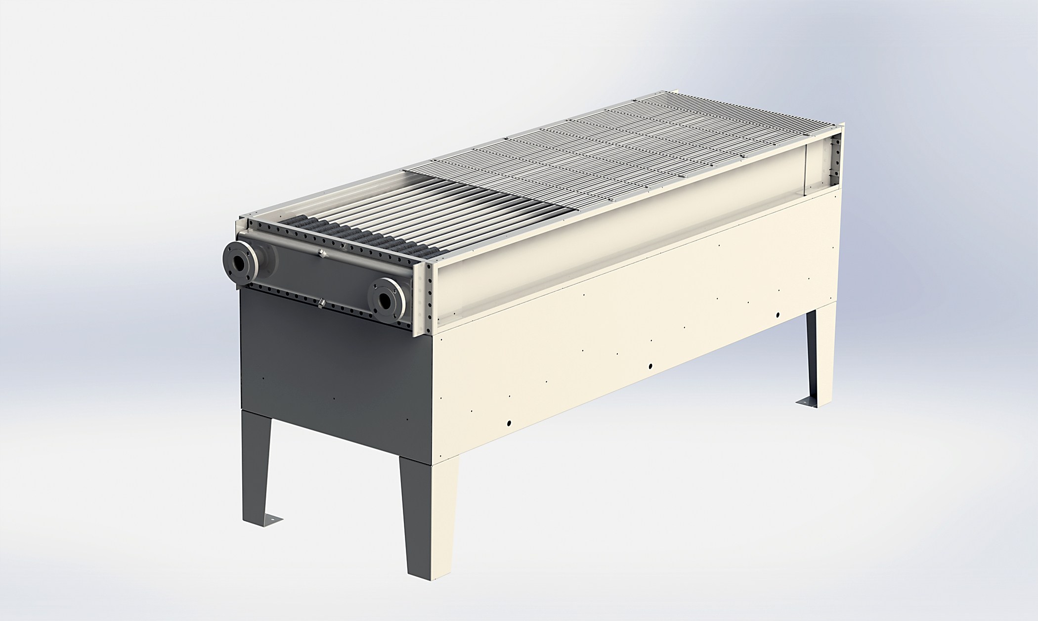
Water cooled heat exchangers are probably the largest culprit of water intrusion in quench oils. While water-cooled heat exchangers are used extensively in Europe, in the United States the use of water cooled heat exchangers is not common. Brazil, China, and India predominately use water to oil heat exchangers due the strong European influence. Water is used in many installations because water/oil heat exchangers are more efficient. Air to Oil heat exchangers are used much more often to cool quench oil in the United States and Canada (Figure 3).
In a typical heat exchanger, water is on one side of a heat exchanger plate, while hot oil is on the other side. Usually, the hot oil side is maintained at a higher pressure than the water side. The claim is that oil would only move to the water side, and water would not enter the oil. This is true assuming that the oil is pumped continually. However, the oil is only pumped during times that the oil temperature exceeds set point and requires cooling.
The water used in cooling quench oil can come from many sources. Closed loop chiller systems are used, as well as city water. Chloride can build up in closed loop systems from treatment for bacteria and biocides. Carbonate build-up can occur from city water. City water also has chloride present. Chlorides tend to attack the heat exchanger material. It is not a matter of if the heat exchanger will fail due to corrosion, but when.
Other sources of water are water cooled bearings, doors, and fans. While the use of water cooled accessories has decreased due to better materials and design, these devices still exist. Water comes from leaking doors, fans or bearings, often occurring during a shut down. Water is left running to minimize corrosion. Leaking occurs and ends up in the quench tank. Pneumatic lines often have water in the compressed air lines. If leaking, water can enter the vestibule and the quench tank. Hydraulic systems using fire resistant hydraulic fluids can often leak. These fluids are often water/glycol mixtures and can end up in the quench tank.
External sources of water can come from many sources. Leaking roofs obviously are a source of water — putting a tarp under the leak is not a long-term fix or even a temporary one. Residual water from poorly reclaimed oils from a parts washer is a common external source. Water is not properly driven off before the water is allowed to reenter the furnace. If oil is sent out to be reclaimed, it is imperative that the oil be checked for water when the tanker returns with the quench oil. There have been several instances where the shipping tanker had residual water in the tanker prior to filling the tanker with the reclaimed quench oil.
Measuring water present is not a simple task. The “Crackle Test” is a method that is often touted to show water in quench oil. However, this test is not accurate and is generally limited to detecting water that is greater than 1,000 ppm. In this test, a small quantity of oil is dropped on a heated (150°C) hot plate. If bubbling or audible crackling of the oil occurs, then water is present. A study of the Crackle Test by TestOil, a commercial laboratory, showed there was a considerable amount of variation in the water detection limit of the crackle test. The range was 100 ppm to 1,800 ppm where samples were known to have water by the Karl-Fischer test but did not crackle. The variability of the crackle test is too large for something as critical as water in a quench oil.
The traditional quantitative method of accurately measuring water is by the Karl-Fischer test (ASTM D6304). This method is very accurate for used oils and can readily determine water contents below 50 ppm. This test is based on the Bunsen reaction between iodine and sulfur dioxide:
SO2 + I2 + 2H2O —> H2SO4 + 2HI
Water can be determined if excess sulfur dioxide is present, and the resultant acid is neutralized by a suitable base. In the Coulometric method, an electric current is used to generate the reagent. The current releases the proper amount of reagent by electrolysis. A variety of different solvents are used to dissolve the oil.
However, the equipment is expensive and requires a laboratory environment. If this equipment is not available, your local industrial laboratory or oil supplier should be contacted should oil be suspected. Water should be tested on a routine basis as part of your maintenance testing protocols.
Conclusions
In this installment, we discussed the dangers of water in quench oil. At low levels of water, the risk of cracked parts or soft spots is likely. At elevated levels of water (greater than approximately 800 to 1,000 ppm water), a severe risk of froth-over type of fires and explosions can occur in your quench tank — with the potential loss of equipment, injury to people, and lost business. Please work with your oil suppliers and your maintenance staff to develop the procedures and protocols to avoid contaminating your quench oil with water. I don’t want to read about another water-related quench oil fire in the news.


