


Both hot and cold forging are batch-type processes in which steady-state conditions are never fully achieved and the initial lubricant supply must perform adequately for the duration of the operation. The lubricant is continuously exposed to changing pressures and velocities, and wear or pickup products in the lubricant also continuously vary, although a dynamic equilibrium may be attained through careful control. The absence of steady-state conditions creates challenges for the systematic analysis of lubrication and wear in forging processes.
In many ways, various forging processes are competitive with one another, and the competitive position of each is greatly influenced by the lubrication system employed. Thus, hot forging followed by finish machining may be replaced by cold forging, with all the associated advantages, provided that a suitable lubricant can be found. Indeed, economy of production has often been the major impetus for the development of new forging processes and associated lubrication techniques.
In forging steels, die life is often controlled by abrasive wear. Thus, die wear and die life are often thought to be synonymous. However, there are other mechanisms by which dies are rendered unusable, including plastic deformation and fatigue failures, induced both thermally and mechanically. If the loads are high or the dies relatively soft, plastic deformation of the dies may occur, making it impossible to impart the desired shape to the workpiece. Thermal fatigue, or thermal cycling, gives rise to superficial
cracks often known as heat checks. Analogous with thermally induced cracking is mechanical fatigue, or cracking, that results from the cyclic application of the forging loads. Although it is not unusual for several of these mechanisms to contribute to die failure, abrasive wear is common to almost all dies and is a significant factor when considering die life for a given process.
Methods to Measure Lubricant Effectiveness and Wear
Measuring Friction for Lubricant Effectiveness
In forging, one of the most common ways to measure friction and thus determine the effectiveness of a lubricant is the ring compression test. This technique was initially applied to cold working [1] and was then further developed and adapted for hot working [2], and offers the great advantage that frictional conditions can be judged from deformation alone, without the need to know the flow strength of the metal. The ring test methodology has been widely studied and implemented to evaluate friction conditions and lubricants in both hot and cold forging applications continuously over the past 60 years, including (for example [3-10]), and remains perhaps the most effective method for evaluating relative friction conditions efficiently.
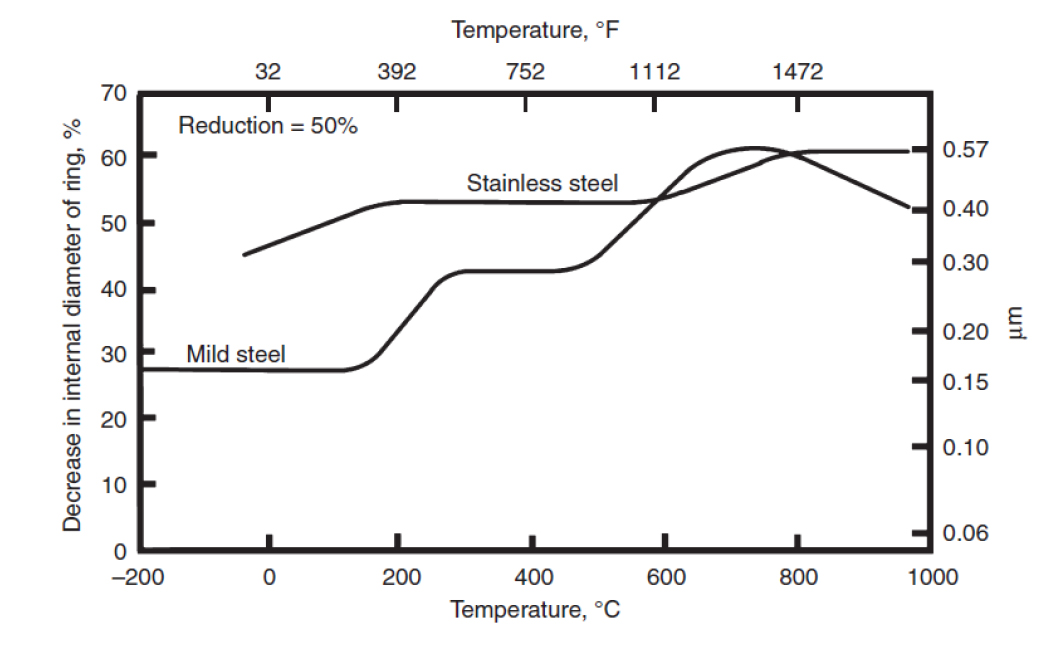
This test is the forging equivalent of forward slip measurement in rolling and is commonly used for lubricant evaluation because simple measurement of the change in internal diameter is sufficient for ranking of lubricant effectiveness. If the specimen geometry is kept constant and the reduction in height is exactly reproduced, a reduced decrease in inside diameter indicates a reduced resistance to shear and thus a lower friction value. With zero friction at the interface, the ring expands as though it were part of a solid disk, the inside diameter increases, and velocities increase radially over the entire surface. With increasing friction, it requires less energy for some of the material to flow toward the center, and the inside diameter of the hole grows less rapidly. With yet higher friction, the internal diameter decreases and both internal and external surfaces barrel. The variation of decrease in internal diameter for unlubricated ring tests on mild and stainless steel are presented in Figure 1 [2].
The ring test is also versatile, as it can also easily be run in production type conditions and is not relegated to a laboratory set of experiments. Hence, the temperature, workpiece, forging dies, speed of deformation, and lubricant used in the production process of interest can be used during the test and measurement of the inner diameter after a given amount of deformation can provide relative effectiveness of the lubrication conditions.
An average external friction coefficient can be quantified if a theoretical analysis that links the final geometry to the frictional balance, such as upper bound or finite element, is applied. The solutions are generally based on the change of internal diameter and can be used to analyze both hot and cold forging processes and may be able to include the effect of chilling on the die. Some solutions allow for barreling of the surfaces, but only finite element analyses can accommodate folding over. Because there is no easy method of calibration, it is difficult to choose the most valid theory, and derived average m (coulombic friction coefficient) or m (constant friction factor) values can easily vary by ± 50 percent simply based on the choice of theory. Nevertheless, the method is well suited for ranking lubricant effectiveness when comparing lubricants.
Other tests to evaluate friction in forging processes have been proposed, such as the tip test [12, 13], the T-shaped compression test [14], the boss rib test [15], the sliding compression test [16], the double cup extrusion test [16, 17], the localized rod-drawing test [19], a compression-torsion- wear test [20], assessment of tribological conditions [21-26], the ball penetration test [27], advanced characterization techniques [28], the upsetting sliding test [29], and the spike forging test [30]. All of these tests either attempt to mimic an actual forging process as closely as possible or assess surfaces to correlate to friction conditions. Like the ring test, these tests combine a theoretical analysis and geometrical measurements to obtain a quantitative value for the friction coefficient or the constant friction factor.
Measuring Wear during Forging
The amount of die material removed because of abrasive wear is directly proportional to the interface pressure and the amount of relative sliding, and inversely proportional to the hardness of the metal surface. Typically, forging dies have a rather complex geometry, so the interface pressure and amount of relative sliding can vary from one area to another. Hence, characterization of abrasive wear in a systematic manner generally makes use of tests with simple geometries to simulate real-world conditions.
Most simple die wear studies have used upset compression of cylindrical billets. In these tests, measurements of die wear were obtained directly by measuring the surface roughness before and after the tests. Upsetting of cylinders on flat dies is a convenient way to forge a large number of specimens for the purpose of testing a die steel. While this test may accurately reflect die wear characteristics in some cases, such as open-die forging, the amount of wear differs in closed-die forging in some important respects: heat transfer and metal flow. Because the flat-bottomed specimen is placed on a flat die prior to forging, a substantial amount of heat can be conducted from the specimen to the die. Thus, at that interface, the specimen is colder and the die is hotter than would be the case in an actual forging die where the irregularly shaped die makes line and point contact with the billet. In upsetting a cylinder, the metal flow is all lateral, or in a direction perpendicular to the ram motion. In real-world forging operations, metal flow will occur in both lateral and longitudinal directions; in some cases, longitudinal flow can be rapid, exceeding by far the velocity of the press ram. In these cases, the sliding velocity at the interface can be an important factor contributing to die wear. Thus, only die wear studies conducted with actual forging dies can give reliable results.
Most evaluations of die wear in impression dies have made use of dies of simple geometry, for example, experiments that forge disks into cups via an extrusion-type process. To keep the component and die temperatures in-line with real-world conditions, die heaters are employed, and a surface analyzer is used to measure the wear of the dies, where the average distance between the worn and unworn profile is taken as the measure of wear. These tests can be used to measure relative wear rates while varying forging conditions, such as lubricant, temperature, die material, workpiece material, and deformation rates, but it may not be possible to directly correlate the magnitude of wear derived from a die wear experiment to a component forging process.
Cold Forging
Lubricants are chosen according to the severity of the operation, defined by conditions such as interface pressures, process geometry, and the extent of sliding and surface expansion. For example, back extrusion of thin-wall deep cup shapes in a high-strength alloy would create severe conditions, especially on the punch end face where the lubricant thins, while forging into a shallow recess or upsetting a cylindrical shape to small diameter-to-height ratio would be less severe. In judging the suitability of lubricants, the magnitude of the forces is often of less importance than the variation of forces and the extent of die pickup.
Mixed-Film Lubrication
In the presence of a liquid lubricant, plasto-hydrodynamic (PHD) lubrication conditions [31] could develop at the beginning of deformation, but evidence indicates that some boundary contact soon occurs. Therefore, it is more relevant to consider mixed-film lubrication conditions.
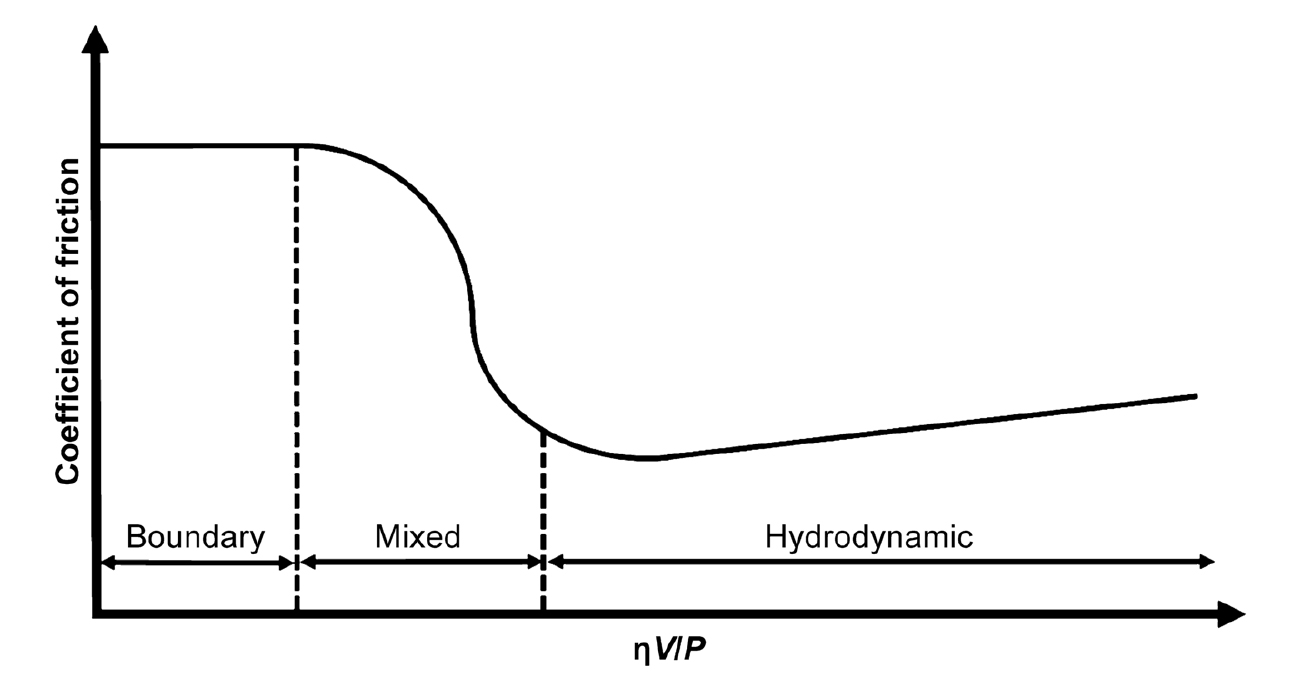
Effects of Deformation and Speed in Upsetting: Experimental results show that, in cold upsetting between flat platens, friction drops while average film thickness increases when lubricant viscosity and speed increase. This is typical of lubrication in the mixed-film regime, corresponding to the descending region of the schematic Stribeck curve; see Figure 2 [32].
The initially entrapped lubricant is sealed at the edges, where a zone of pure boundary contact develops [33]). Thus, lubrication is mixed in the macroscopic sense, with PHD conditions in the center and boundary conditions at the edges. As deformation proceeds, the film thins as it follows the expansion of the end face, and roughening of the workpiece results in a shift toward conventional (microscopic) mixed-film lubrication in the original PHD zone.
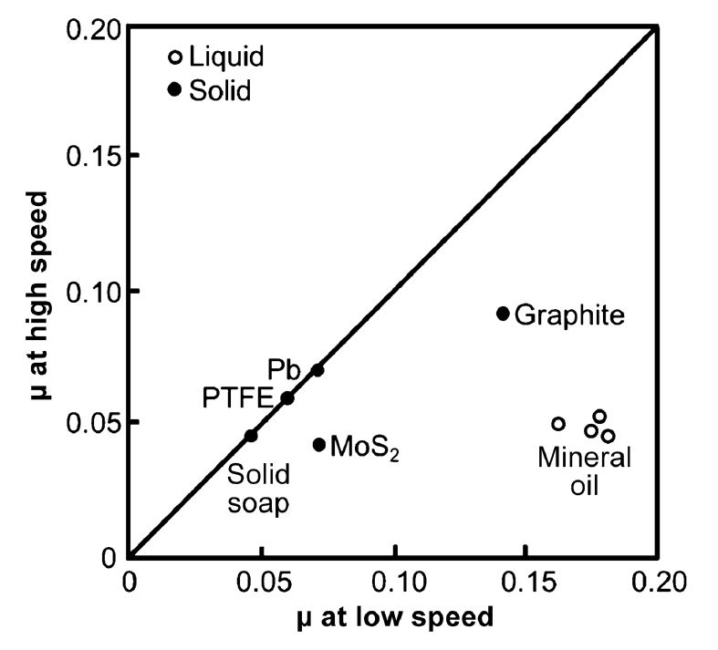
If desired, an average friction coefficient m can be derived from ring compression or, less reliably, back-calculated from mean pressures in cylinder upsetting. However, the magnitude of m in itself conveys little about the operating mechanism; it is more useful to observe surface deformation and to assess the area of boundary-lubricated surface. Most of the frictional stress is generated on the boundary-lubricated surfaces, with hydrodynamic pockets contributing only negligible amounts. Experimental observations indicate a wide range of m according to process conditions. At sufficiently high impact velocities, such as those attained in high-energy-rate forging equipment or in conventional hammers (impact velocities in excess of 5 m/s), even water will generate PHD films [34]. At the lower speeds more typical of mechanical presses, upsetters, and hydraulic presses, oil-base lubricants are needed. High viscosity alone can ensure film formation, but a high speed is needed when viscosity is low. Whenever ηV is high enough, the squeezed film reduces friction to typically µ = 0.05, Figure 3 [35], irrespective of the die/workpiece material combination. Therefore, adequate viscosity is crucial in forming of nonreactive metals, and in lubricating the freshly formed end faces in forging from a bar.
In many practical applications, the surface roughening resulting from the presence of a PHD film is objectionable, and viscosity is reduced so that most of the interface is in boundary contact. Therefore, friction cannot drop below µ = 0.05 and is typically on the order of µ = 0.1. Additives are then important. In their absence, die pickup occurs toward the edges of the workpiece if adhesion between die and workpiece is high, as in upsetting of aluminum and, to a lesser extent, stainless steels and titanium. Friction could then gradually rise to values as high as µ = 0.3. Less adhesive combinations produce lower coefficients of friction, on the order of µ = 0.1 to 0.15, as in upsetting of brass or copper. Nevertheless, additives are required for those metals because die wear could otherwise become too severe. Contact in a single stroke is too brief to activate extreme pressure (EP) lubricants, and it is likely that the necessary cumulative time and temperature combination can be ensured only on the die surface in the course of several hundreds or thousands of contacts. Protection of the die during the first few contacts is particularly important in forging from a bar with unprotected, freshly sheared end faces, until reactions are initiated and friction polymers are formed. The effectiveness of boundary additives increases with increasing molecular chain length, and saturated fatty acids reduce friction more than their unsaturated counterparts. However, it is not always clear whether this is purely a boundary effect or is also attributable to the higher viscosities of the more effective agents. Fatty oils find use, too, for both their viscosities and their boundary properties.
At the low speeds typical of many laboratory experiments, boundary lubrication effects become more pronounced, and hydrodynamic effects are suppressed. Therefore, many of the m values reported in the literature are higher than the most likely values attained under production conditions. The effect of speed depends also on lubricant rheology. Thus, a highly viscous or semisolid lubricant such as lanolin may give lower friction at low speeds than viscous oil yet result in higher friction at high speeds where its shear strength is higher than that of an oil film.
Effects of Process and Surface Geometry. As in all PHD lubrication, geometry plays an important role. The shape of the tool is dictated by the configuration of the finished part, but, nevertheless, elastic deformation of even a flat tool can help in entrapping the lubricant and may be a major source of squeezed-film formation in low-speed compression [36]. A squeezed film is formed even between a spherical tool affecting a flat workpiece. For the same base viscosity, naphthenic oils, with their higher pressure-viscosity coefficients, give better developed films than paraffinic oils, and the films are better able to resist breakdown on subsequent sliding. Narrow weight ranges of molecules are more resistant to breakdown than oils of wider molecular weight distribution.
Entrapment of a viscous lubricant by mechanical means is particularly effective. Pre-machined pockets are not practical for production purposes, but grooving of the end faces is acceptable when other measures prove inadequate. The latter is a valuable method for reducing friction when determining the flow strength. The volume of such grooves gradually diminishes during the compression, and the displaced lubricant flows over the ridges to provide micro-level PHD lubrication. Grooves are most effective if they are wider and deeper than the natural roughness that develops with the given lubricant, and thus grooves should be smaller for a lighter lubricant and a finer-grain material. Pyramidal indentations created in the surface produced a similar effect [37]. Small, closely spaced indentations are better in reducing friction and preventing pickup. In general, workpiece roughness is helpful, whether produced by prior working, pickling, shot blasting, or machining, as long as the finish is nondirectional or, if it is directional, as long as the grooves are perpendicular to the major sliding direction.
Die surface roughness is generally harmful in the mixed-film regime, but moderate roughness is helpful if the lubricant polymerizes or wear products form, provided that no pickup occurs during the first few strokes in a production run. In most laboratory work, the dies are cleaned after every test, and too few cycles are performed to attain steady-state conditions. For this reason, too, the condition µ = 0.05 likely occurs in production environments much more frequently than published laboratory results would indicate.
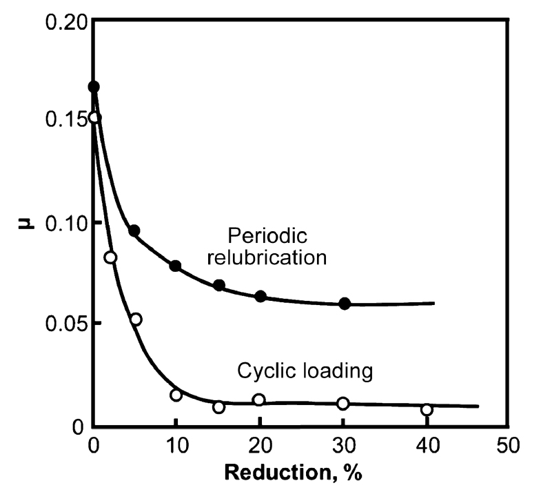
During cylindrical compression, the growth of the entrapped squeezed film seldom keeps up with the expansion of the end face of the workpiece, and therefore the boundary-lubricated edge zone broadens, the average µ rises, and pickup may occur. Friction can be kept low and pickup minimized if the squeezed film is periodically re-established. This can be achieved in several ways, Figure 4 [38]. Compression can be interrupted, and the die and workpiece surfaces are relubricated. Such incremental compression is acceptable for laboratory flow-strength determination but is impracticable for production. Another way is that vibrations may be superimposed on the tooling. The squeezed film is re-established if the tool lifts away from the workpiece. This effect is particularly noticeable when the workpiece is reactive with the lubricant and adheres to the die. Vibrations at both low (10 to 50 Hz) and higher frequencies have been found to be effective in reducing friction and barreling, although equally good results can usually be obtained by choosing a better lubrication system. Much of the force reduction reported by various workers can be attributed to a replacement of the static compression force by a vibrational force.
For plane strain compression, lubricant viscosity and additive effects are the same as in upsetting of a cylinder. A lubricant film forms around the neutral line and is hydrodynamically compressed. The width of this zone increases with increasing speed and viscosity. Compared to cylinder upsetting, lubricant additives are more effective because the freshly formed metal surfaces slide over the edges of the tooling. Tool pickup becomes immediately apparent because of scoring on the deformed surface.
Solid Film Lubrication
The high pressures and large surface expansions typical of extrusion-type cold forging often lead to pickup and tool wear with liquid lubricants, and therefore solid or bonded lubricants are used. For maximum benefit, all surfaces of a precut billet or slug must be coated. In forging from bar or wire, precoating of the bar or wire is beneficial if severe cold extrusion is combined with moderate back extrusion or upsetting for which a liquid lubricant is supplied at the cold header. In judging the severity of the operation, it should be remembered that die temperatures reach 100 to 200°C (210 to 390°F) under steady-state conditions if workpieces follow in rapid succession and heating due to plastic deformation is substantial. Many kinds of solid and semisolid lubricants have been used, and various lubricants are tailored to individual metals and to specific severity of the operation.
The major advantage of metal films deposited on the billet is that they follow the expansion of the end face in upsetting and flow with the workpiece. Separately interposed metal or polymer films are cut through at the edges in upsetting and are only moderately effective even though their shear strength is low, because friction on the unlubricated regions raises the average coefficient of friction. Metal as well as polymer films can be modeled as strain- rate-sensitive substances. The main danger with polymer and layer-lattice films is localized breakdown, which allows metal-to-metal contact and die pickup. Transport of the film and thus resistance to breakdown are improved with appropriate workpiece surface roughness, and moderate die surface roughness oriented perpendicular to the sliding direction can also be beneficial in providing lubricant reservoirs. For this to occur, however, the film must be thick enough to provide full separation.
Semisolids such as soaps, waxes, lanolin, tallow, and other fats can be deposited in a thin film from a solvent, although they are not necessarily much better able to resist wiping off than are some of the more viscous liquids. For heavier duty applications, these lubricants must be transferred to the surface by a lubricant carrier or, for exceptionally severe conditions, by a conversion coating. The most severe conditions may justify use of MoS2, deposited on top of the soap. A phosphate film itself is not a lubricant and ensures low friction only when impregnated with a semisolid. Lubricants without zinc phosphate precoatings have been evaluated and have been found to be comparable to or better than the precoated systems [39].
The film thickness must be kept at the minimum value that still ensures adequate lubrication, because excess lubricant builds up in recesses in the die, resulting in underfilled forgings and can lead to undesirable roughening of the surface. For studies of surface roughness, the lubricant film (including conversion coating) must be removed. However, the residual lubricant film itself gives valuable clues regarding the lubrication mechanism and the adequacy of protection against metallic contact. Predictions for surface roughness during cold forging have been proposed [40].
In contrast, some deliberate and controlled roughening can be beneficial in improving the lubricant behavior and reducing friction. A lubricant carrier using surfaces with small pores has been developed with some success [41].
Die Wear
The basic concepts behind die wear were presented previously. Cold forging production runs are usually long (tens of thousands of parts), and die lives of hundreds of thousands of parts are sought in cold extrusion with steel dies, and lives three to five times longer with tungsten carbide dies. Thus, the die material must be hard enough to resist abrasion and reactive enough to allow extreme pressure (EP) lubricants to function but without causing excessive chemical wear. The ultimate tool selection is made on the basis of long runs, and simulation has helped in die selection.
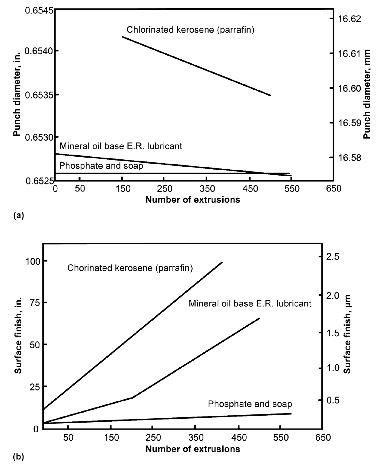
Wear, judged from the change in punch diameter, is greatest with chlorinated paraffin in a light kerosene base, much less severe with a more viscous commercial cold heading lubricant containing an unspecified EP agent, and negligible with a phosphate/soap system, Figure 5(a) and (b), [42]. Surface finish specified as peak-to-valley average (Rt), reflects the roughening that normally accompanies die wear.
Hot Forging
Hot forging is the most ancient of all metalworking processes, yet it is also the one for which lubrication studies have been difficult. The reason is, of course, that in drop (hammer) forging of steel, the new surfaces generated during deformation are exposed to air between successive blows, and thus they reoxidize before making the next die contact. Die filling is not necessarily aided by lubrication. With hydraulic and, particularly, mechanical presses and for the forging of light metals and difficult-to-forge materials, that lubrication becomes important.
Workpieces are heated to typical hot working temperatures, but dies are usually substantially colder. Therefore, a lubricant not only should ensure die/workpiece separation and lower friction but preferably should also act as a heat insulator. Excessive heating of the dies leads to die damage and wear, and the lubricant or its carrier should also perform a cooling function. High temperature at the interface severely limits the choice of lubricant.
Solid Film Lubrication
With occasional exceptions, such as in forging of aluminum or magnesium, the lubricant is applied only to the die because it would be destroyed in the course of preheating the workpiece. The die itself is usually preheated or reaches some steady-state temperature during forging, and therefore the carrier is chosen with wetting of the die surface in mind. Oils and greases used to be preferred, but occupational health and ecological considerations favor aqueous lubricants. Furthermore, capillary forces that aid alignment of platelets are less effective while the oil decomposes on heating. Overviews of things to consider when selecting a lubricant for hot forging have been developed [43].
Effect of Temperature. Lubricant breakdown and oxidation are functions of contact time, die and workpiece temperature, and surface deformation and sliding. For a given contact time, various lubricants break down at different temperatures. The higher the temperature is, the more rapid will be the breakdown.
Effect of Heat Transfer. A potentially confusing factor is chilling of the workpiece on the die surface. This restricts deformation just as much as friction does, and it affects measured interface stresses. The relationships are not straightforward because oxides, which are heat insulators, interact with the lubricant to determine the rate of heat transfer. These effects have been most extensively studied in forging of steel, although they are equally important in forging of other metals.
A thicker oxide is, in general, a better heat insulator, and the reduced heat flow reduces the temperature gradient in the surface layer of the die. Breakup of the oxide film greatly increases heat transfer, and therefore the rate of heat loss increases suddenly when pressure is applied and plastic flow begins, irrespective of whether the workpiece is of steel or aluminum. This effect is quite dramatic when a workpiece with a rough surface is loaded and deformation of asperities creates oxide-free junctions. Heat transfer is then the same with or without a lubricant, as observed for graphite on steel and MoS2 on aluminum, and approach values of completely uninsulated surfaces. With increasing strain, more fresh surface is exposed, and heat transfer rates increase further, if possible.
Heat transfer is also a function of contact time and thus of forging speed. Temperature gradients are greater at higher speeds, and die surface temperatures can reach relatively high values. Cumulative contact time is, however, less on the hammer, and this keeps bulk temperatures lower.
An important lubricant function is cooling of the die. Aqueous lubricants are the most effective and reduce the bulk temperatures of hammer dies — with their steeper temperature gradients — more than those of press dies. It is not unusual to find that heat-transfer rates increase with lubrication, because the insulating properties of the oxide are destroyed when it is impregnated with a more conductive substance — especially with a liquid carrier such as water, oil, or grease. Only when the carrier forms a heat-insulating film is heat transfer reduced.
Lower heat transfer rates do not necessarily mean lower friction. Friction reaches a minimum at an oxide film thickness of about 50 µm, climbs to an intermediate maximum at 150 µm, and declines further at 250 µm. Lower friction is associated with a higher FeO content in the scale.
Similar effects must apply also to oxides of other workpiece materials, although the relative degrees of hardness and ductility (or, rather, brittleness) of various oxides are quite different. Oxides of other metals may also be interposed as lubricants but are not capable of following the surface extension of the workpiece.
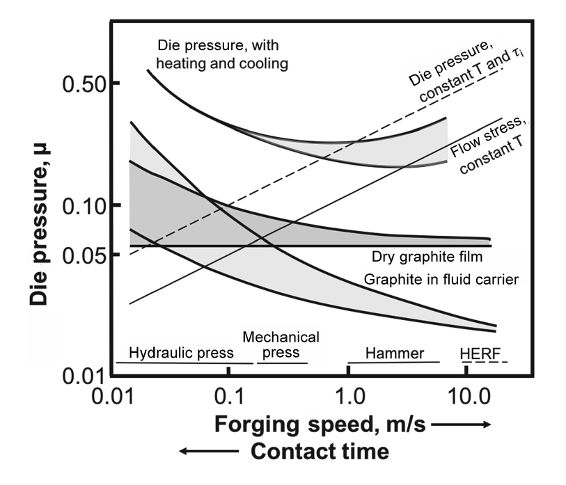
Effect of Forging Speed. With higher forging speeds, several effects take place simultaneously. The flow strength of the workpiece increases because of the higher strain rate, resulting in increased die pressure, but if heat generated is retained sufficiently, it may also result in counteracting decreases in flow stress and die pressure; see Figure 6 [11]. The contact time is reduced and cooling minimized, counterbalancing to some extent the increase in flow strength due to higher strain rates. The time of lubricant exposure to high temperature is reduced. In the presence of a liquid carrier or carrier residue, a squeezed-film effect develops. The combination of the above effects generally reduces friction at higher speeds. This reduction is observed even with unlubricated but oxidized steel workpieces. Competing with the squeezed-film effect is lubricant breakdown due to oxidation and thermal decomposition. At given forging and die temperatures, lower speed results in longer contact time and more damage to the continuity of the film. Depending on the nature of the viscous carrier, friction may even become higher than with a dry film. Die temperature and the time elapsed between lubricant application and contact with the workpiece play decisive roles in the evaporation of the carrier. With increasing interface temperature, film damage increases, and thus the increase in m is greater.
Interactions of oxides with the lubricant also enter into the speed effect. A heavy oxide film interferes with a dry colloidal graphite lubricant. A thin (less than 25 µm) oxide film gives lower friction with dry graphite at both hammer and press speeds. A thick oxide film can, however, negate the squeezed-film effect.
Effects of Die Geometry and Temperature. Lower friction at higher forging speeds does not necessarily mean lower forging forces, because the increase in flow strength often outweighs the effect of the lower pressure-multiplying factor that accompanies a lower friction. Thus, for a given lubricant, forging on high-energy-rate equipment results in higher forces than does forging on a press. A lubricant film with good heat insulation brings the situation closer to adiabatic conditions, and the greater temperature rise may counterbalance the strain-rate effect. Results are, therefore, highly dependent on experimental conditions. An optimum speed in terms of minimum forging load and best die filling can sometimes be found.
In judging the effectiveness of a lubricant, one must keep in mind that entirely different criteria apply to various forging geometries. In upsetting and ring compression, the predominant variable is end-face expansion, and this is promoted by lubrication. In true closed-die (trapped-die) forging, the major deformation mode is extrusion, into a narrowing gap when draft angles are used. Interactions among oxides, lubricant, and forging speed can become difficult to separate. In conventional impression-die forging the extrusion effect is combined with upsetting (and lateral extrusion) of the flash. The short contact time in the hammer aids die filling and neutralizes the friction effect.
Die temperature is a most significant factor, but the effects are complex. Higher die temperatures result in less cooling and thus facilitate material flow, especially in impression- and closed-die forging. If increasing interface temperature results in an earlier breakdown of the lubricant, interface sliding decreases, and less outward expansion is found in ring compression. Some lubricants fail to wet a hotter die, and friction increases.
Effect of Application Method. Even the best lubricant will fail if it is deposited discontinuously. At the same time, excessive coating thickness can lead to lubricant accumulation, unfilled forgings, and poor surface quality. Therefore, controlled deposition is essential.
Hand application by swabbing is still practiced but is not satisfactory, particularly with aqueous lubricants. Automated mechanical methods of application have been developed. A good application system must prevent settling out of solids in the holding tank, ensure reliable and uniform atomization (breaking up of the liquid droplets) by mechanical means or air pressure, and deliver the fine droplets to the die in a controlled manner. Hand-held spray heads suffice for production at lower rates, but mechanically operated stationary or oscillating spray bars are essential for high production rates. Spray heads with sufficiently large orifices can be kept open if air is blown through them after each lubricant application.
Thick Film Lubrication
At hot forging temperatures, glass or similar inorganic substances can produce a thick film lubricant. The forging process imposes some special requirements. In both isothermal and nonisothermal forging, any accumulation of lubricant residues in the die cavity results in underfilled forgings. Therefore, the lubricant must be applied to the workpiece only, in the form of a thin coating. The glass should wet the workpiece in order to follow surface deformation, but it should do so without attacking (corroding) the die or the workpiece. It should adhere to the workpiece sufficiently to be lifted out with the forging. If glass adheres to the die, it should allow ejection of the workpiece without excessive force and without long, strong stringers. In nonisothermal forging, the heat-insulating capacity of the lubricant should be high. Because glass is not capable of preventing pickup if the film is locally damaged, additional protection must be secured by adding a compatible parting agent such as BN to the glass and/or by applying a thin, dry or grease-base graphite coating to a colder die. Isothermal forging temperatures are too high for graphite to survive, and BN serves as a useful parting agent.
Lubricant Variables. There is no optimum viscosity, although recommendations are 10 to 100 Pa·s at the workpiece temperature. More relevant is the viscosity at the average of the die and workpiece temperatures. In nonisothermal forging, the workpiece surface temperature tends to drop with a good heat-insulant liquid film, but it can actually rise when the film breaks down and high friction generates heat. For isothermal forging, it is more meaningful to relate glass viscosity to the flow strength of the material. There is no definite minimum film thickness, but typical values are approximately 0.05 to 0.1 mm in forging. Excessively thick films lead to surface roughening and glass buildup in the die.
Some lubricants other than glass can serve as viscous fluids showing diminishing film thickness on increasing workpiece temperature. Wetting of the workpiece surface by the glass and protection during preheating are important, but the glass with the best protective properties is not necessarily the best lubricant on steel. The best protection is ensured by preheating in a glass bath, the glass then serving also as a lubricant. Glass is a good heat insulator and reduces cooling rates during transfer from the furnace.
Although the ring test has been used to evaluate the frictional conditions in hot forging, other tests have been developed. The warm hot upsetting sliding test [44] is one such test, and die wear during warm forging can be quite different from that occurring during hot forging [45]. Attempts to mitigate the environmental effects and lubricant disposal issues have been undertaken [46]. International focus on this issue is also a concern for many researchers and many forging facilities, with interest increasing recently [47–51].
Die Wear
The life of hot forging dies ranges from a few hundred to some tens of thousands of parts. It is short enough to have prompted serious investigations into causes of die wear, especially because die costs account for some 15 percent of total production costs.
High die temperature is destructive because the die surface loses strength in a thin layer, which makes it less resistant to abrasion and plastic deformation. Therefore, wear under unlubricated conditions is found to be inversely proportional to die temperature. Conversely, rapid heating above the transition temperature of the die surface on contact, followed by quenching by the cold backing, leads to the formation of a brittle, hard (martensitic) layer, which is prone to fatigue but more resistant to abrasive wear.
The main variable is die temperature. Die life decreases with increasing weight of the forging, because the higher heat content of a larger piece results in higher die temperatures. Interruptions of the smooth flow of production are harmful, because they increase temperature excursions. Contact (dwell) and cycle times affect bulk die temperatures and surface temperature gradients in the die. Contact time increases with the number of blows on a hammer, leading to more severe wear if the hammer is too small for the part. Wear is especially severe in the finishing blows on strong alloys. Stickers are most harmful and result in much- reduced die lives, especially in press forging without an ejector. Excessive temperature is harmful, but so are excessive temperature excursions. Thermal shock and thus thermal fatigue are minimized by appropriate preheating of the die, preferably with an evenly distributed heat source (gas or electric) rather than with a localized high-temperature source (such as a hot workpiece). The optimum preheating temperature is a function of both die and lubricant composition. Die configuration, together with lubrication, determine material flow. More complex parts need higher pressure and more blows to fill in a hammer, are more likely to stick, and throw more flash, resulting in increased wear. A wider flash land wears less but at the expense of higher cavity pressure. The surface topography of milled dies has been found to influence the wear of hot forging dies [52].
Factors Affecting Abrasive Wear
Die Material
Of all the factors that influence abrasive wear, the one easiest to understand and quantify is that of die material and hardness. In general, increasing alloying content and die hardness both tend to increase the resistance of forging die steels to abrasive wear. Low-alloy die steels, such as 6F2, 6G, and 6H1, generally have poor resistance to wear as compared to hot-work die steels, such as H13 and H26. This difference is because the microstructures of the latter steels are not only inherently more resistant to wear, but they also tend to be more stable at higher temperatures. Low-alloy steels have far inferior wear resistance as compared to hot-work die steels because alloying led to higher hardness and the ability to retain strength at high die temperatures.
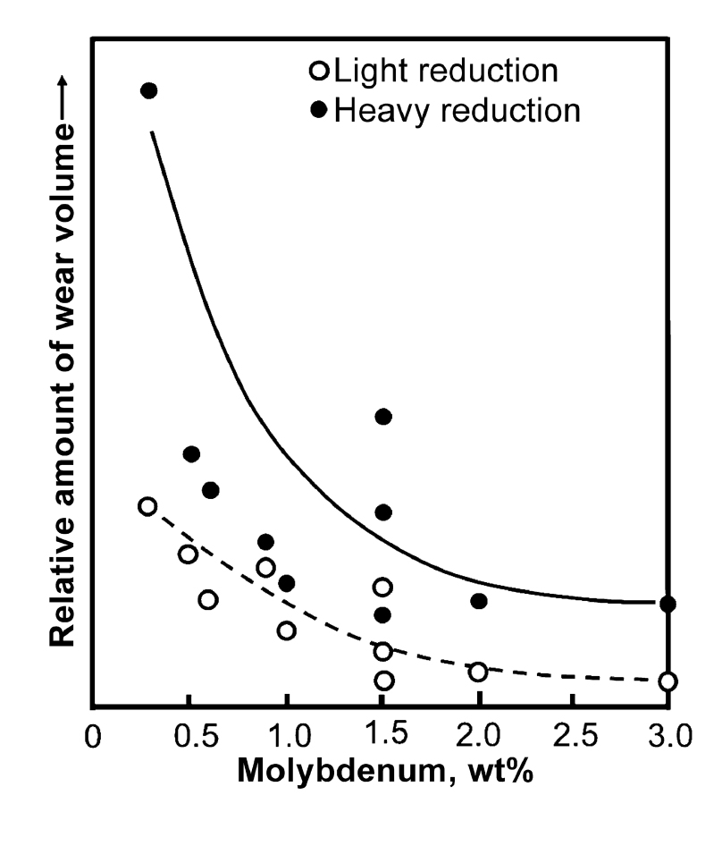
The effect of various alloying elements on wear of steels has been studied by various authors. The wear resistance increases with increasing contents of carbon and carbide-forming elements, and the presence of elements that are not carbide-forming in martensitic die steels may even be detrimental [53]. Of the carbide-forming elements, greater wear resistance is developed in the order of chromium, tungsten, molybdenum, and vanadium, with the effectiveness in reducing wear being in the ratio of 2:5:10:40, respectively, when the die temperature is between 250 and 550°C (480 and 1,020°F). Thus, vanadium and its associated carbides are eight times as effective as tungsten and its carbides in reducing wear. Good wear resistance is obtained when the total alloy content is in excess of 3 percent. Molybdenum has a strong effect on reducing wear, but quantities in excess of 2 percent are not needed. An example showing wear as a function of alloy content (Mo wt percent) is given in Figure 7 [54].
The nickel-base alloy Nimonic 90 has a wear resistance between that of an H12 and H19 steel at a die temperature of 255°C (490°F). This observation is an important one since the nickel-base alloys are generally many times the cost of the die steel alloys and are harder to machine.
Die Hardness
Die hardness is another factor whose influence on abrasive wear is easy to quantify. There are two basic processes involved [56]. The first is the formation of plastically deformed grooves that do not involve metal removal, and the second consists of removal of metal in the form of microscopic chips. Because chip formation, as in metal cutting, takes place through a shear process, increased metal hardness could be expected to diminish the amount of metal removal via abrasive wear. This trend is exactly as observed experimentally and in production environments.
The dependence of wear rate on hardness is greatest for low-alloy die steels such as 6F2 [53]. There is a correlation between hardness and wear of die steels with microstructures different from the typical die steel structure of tempered martensite. It has been found that the isothermal heat treatment of steels to produce lower bainite results in better wear resistance. Supposedly, this effect is a result of the fact that isothermal transformation/hardening causes fewer stresses and microscopic cracks (which promote abrasive failure) than does a thermal martensitic transformation.
Workpiece Temperature
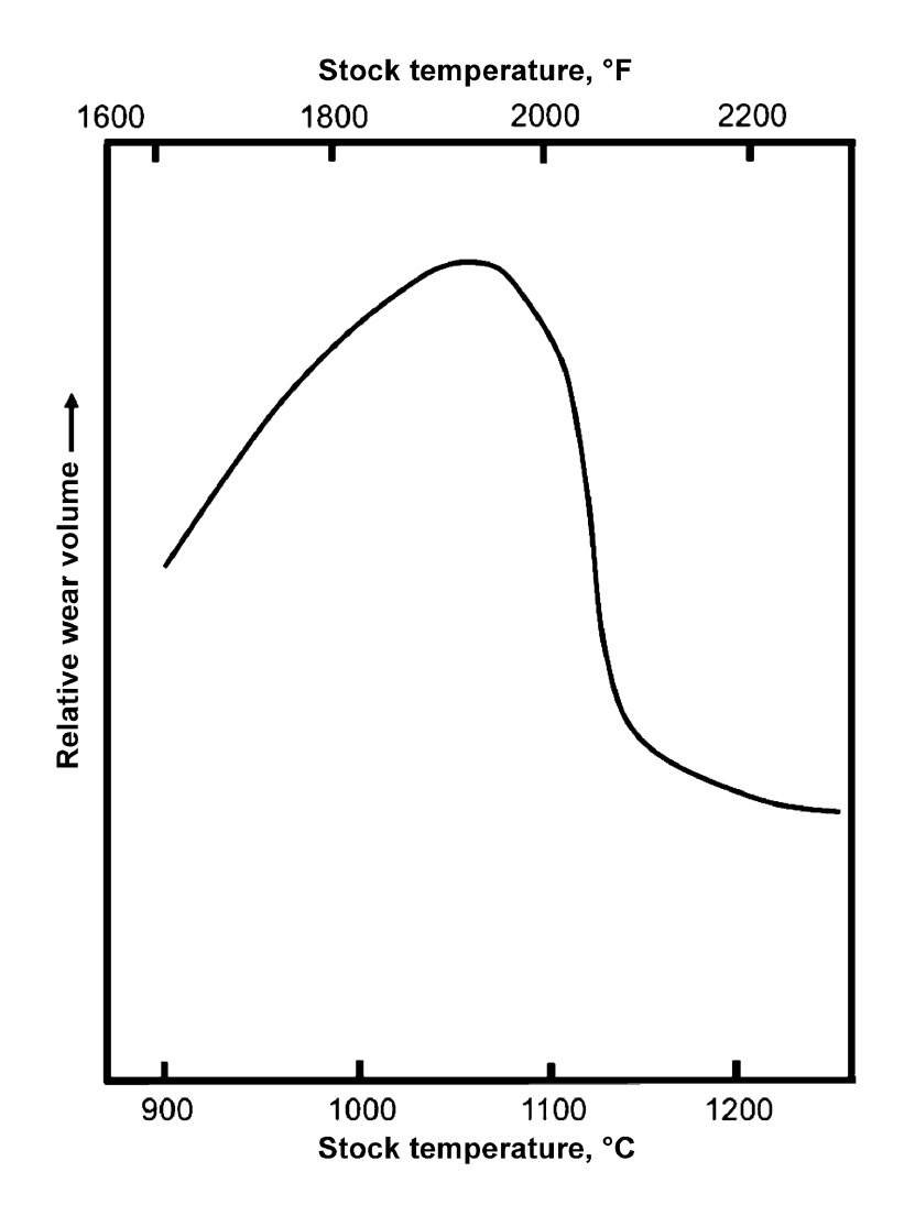
During forging of steels, wear increased at first with billet temperature up to 1,100°C (2,000°F) and then decreased with increasing temperature, as shown in Figure 8. The initial increase can probably be attributed to the increase in the amount of scale on the billets, which acts as an abrasive during the die wear process. However, above 1,100°C, the flow stress drops off rapidly enough to minimize the interface pressure during forging and, therefore, decrease the effect of scale [58].
Lubrication and Die Temperature
The effects of lubrication and die temperature on die wear have been interpreted in a variety of often-conflicting ways. This is because lubricants and die temperature influence (a) lubricity, and hence the amount of metal sliding during forging, (b) the interface pressure during deformation, and (c) the heat transfer characteristics between the dies and workpiece during conventional hot forging. Heat transfer is important not only through its influence on heat absorption into the dies, and thus thermal softening and decreased wear resistance of the dies, but also through its effect on the performance of the die and billet lubricants themselves.

Investigations into the effect of lubrication on die wear in simple upsetting have shown that wear is greatly increased when the dies are lubricated versus when they are not [59], as shown in Figure 9. The same phenomenon was also found during upset successive lots of 1,000 samples each on a flat die in a mechanical press. In these tests, the amount of wear was greater for the lot involving lubricated compression tests [57]. From these findings, one might conclude that wear increases with lubrication because of increased sliding and that lubrication is detrimental in forging. This point is clarified, however, by calculating the amount of wear for equivalent amounts of metal flow past a given point; lubrication reduces wear by a factor of three when compared to forging without lubrication. Moreover, in closed-die forging, the amount of metal sliding is fixed by die and preform design and not lubrication. Thus, the amount of sliding over the flash land, where wear is usually greatest, depends on the amount of flash that must be produced and not on the efficiency of the lubricant employed. Because the amount of flash will be roughly the same with or without lubrication, employing lubricants in closed-die forging should reduce abrasive wear of the flash land and other parts of the die cavity.
The interaction of lubrication and die temperature effects was demonstrated [60] in upset tests on a high energy rate forming (HERF) machine. These tests were run with various bulk die temperatures, dwell times, and cycle times. Dwell time in the HERF operation includes a short forging phase, a somewhat longer “bouncing” phase, and an extended “after-forging” phase during which the dies and billet are in contact under low pressure. Results established that die wear after upsetting of 1,000 billets decreased with increasing die temperature. These results were correlated with decreased amounts of sliding at higher die temperatures due to an increase in the coefficient of friction.
Increasing dwell time increases die chilling. As a result, metal flow is hindered, and die wear is reduced. Increased cycle time (time between forgings) tends to have the reverse effect of increasing dwell time (that is, it increases die wear because of lower coefficients of friction and more sliding). However, these effects have been found to be slight in upset tests conducted in a HERF machine [60].
A striking die wear concern is the generally higher wear experienced by the top die versus the lower die, which is most noticeable in their lubricated upset tests, also shown in Figure 9. This difference can be attributed to greater chilling on the bottom die because the hot workpiece was placed on it prior to forging. This higher temperature could, therefore, have been expected to lead to greater friction, less sliding, and thus less abrasive wear than the top die experienced.
From a practical standpoint, increased production rates in a forge shop may be expected to lead to lower die life. Increased die temperature is often used to increase production rates. In forging under production conditions, the die surface temperature observed between two consecutive forging blows seems to remain unchanged throughout a production run. During the actual forging operation, the die surface temperatures increase and reach a maximum peak value and decrease again when the dies are separated and the forging is removed. In case the forging “sticks” in one of the dies, the peak surface temperature of that die may increase further and contribute to die wear. Therefore, in conducting die wear studies, it is suggested that an ejector be used to remove the part after forging, so that die temperatures do not increase because a forging sticks in the die. In forging of steel at 1,200°C (2,190°F) with dies at about 250°C (480°F), the surface temperatures will reach approximately 750°C (1,380°F) if perfect and ideal contact occurs between the forging and the die. In reality, however, due to scale and oxidation at the die and material interface, the peak surface temperatures during forging reach 500 to 600°C (930 to 1,110°F) in mechanical presses and 650 to 700°C (1,200 to 1,290°F) in hammers.
The effects of sliding on die wear are also qualitatively well known in forging practice. These effects are taken into account in designing preforms to ensure that more “squeezing” and less lateral flow and sliding action take place during finish forging.
Improving Resistance to Abrasive Wear
The most direct method to improve die wear is to employ a die steel that is more resistant to wear, that is, one that is harder and that retains its hardness at high die temperatures [61]. This could mean changing from a low-alloy die steel to a chromium hot-work die steel. The decision to make such a change should be based on the suitability of the new die steel itself in the forging operation and the trade-off between expected increases in die life and increases in material (and machining) costs. More recently, computational analyses have resulted in improved simulation capabilities, which allow for improved die design to reduce conditions that are conducive to abrasive wear [62–73], although the details of local pressure, temperature, and friction conditions coupled with the precise material response to these conditions is critical to the ability to accurately simulate any forging process. Although computational analyses are advancing, experimental evaluations of wear remain an active area of investigation (for example [74–77]), and precise mechanisms of wear and local stress, temperature, and friction conditions are often unknown.
Coating, hardfacing, and surface treatment of forging dies often can be employed to improve wear resistance as well. Some specific coating and hardfacing alloys and surface treatments such as nitriding and boriding are beneficial. These include the use of chromium and cobalt-base coatings, weld deposits of higher-alloy steels onto low-alloy steels [78], weld deposits of nickel and cobalt hardfacing alloys on die steels [79], ceramic coatings, physical and chemical vapor deposition coatings [80, 81] and surface nitriding [82]. Studies have been done to show the effect of lubricant and coating on the life of the die [83].
Another means of reducing wear in the forging of steel involves reducing the scale on heated billets; scale acts as an abrasive during the sliding that occurs between the dies and workpiece. Poor control of scale can reduce die life as much as 200 percent. Methods of reducing scale are relatively obvious and include:
- Using induction heating.
- Using a reducing, or inert, furnace atmosphere.
- Using a billet coating to prevent oxidation.
- Minimizing time at temperature in the furnace.
One final means of decreasing the problem of wear is through improved redesign of the blocker shape. This approach is an important consideration because wear is strongly dependent on the amount of sliding that occurs on a die surface. Thus, it is possible to reduce sliding, thereby reducing wear, by redesigning the blocker shape.
Acknowledgments
Partial support for this work from the Advanced Steel Processing and Products Research Center at Colorado School of Mines is gratefully acknowledged. Special thanks are extended to Professor John Schey for his outstanding work Tribology in Metalworking: Friction, Lubrication and Wear (ASM International, 1983) from which information has been extracted and which forms a foundation for this article. The authors also thank R. Shivpuri and S.L. Semiatin for their article “Friction and Wear of Dies and Die Materials” in ASM Handbook, Volume 18: Friction, Lubrication and Wear Technology, (ASM International, 1992), which also provides foundational information for this article.
References
- M. Kunogi, J. Sci. Res. Inst. (Tokyo); Vol 50, 1956, p 215–246.
- A.T. Male and M.G. Cockroft, J. Inst. Metals, Vol 93, 1964–1965, p 38–46.
- B. Avitzur, Metal Forming, McGraw-Hill, New York, 1968.
- C.H. Lee and T. Altan, Influence of Flow Stress and Friction Upon Metal Flow in Upset Forging of Rings and Cylinders, J. of Engineering for Industry, Vol 94 (No. 3), 1972, p 775–782
- V. Nagpal, G.D. Lahoti, and T. Altan, A Numerical Method for Simultaneous Prediction of Metal Flow and Temperatures in Upset Forging of Rings, J. of Engineering for Industry, Vol 100 (No. 4), 1978, p 413–420.
- N.A. Abdul, Friction Determination during Bulk Plastic Deformation of Metals, Annals of the CIRP, Vol 30 (No. 1), 1981, p 143–146.
- R. Lakshmipathy and R. Sagar, Effect of Die Surface Topography on Die-Work Interfacial Friction in Open Die Forging, International Journal of Machine Tools and Manufacture, Vol 32 (No. 5), 1992, p 685–693, http://dx.doi.org/10.1016/0890- 6955(92)90023-a.
- H. Sofuoglu and J. Rasty, On the Measurement of Friction Coefficient Utilizing the Ring Compression Test, Tribology International, Vol 32 (No. 6), June 1999, p 327– 335, https://doi.org/10.1016/S0301-679X (99)00055-9.
- Z.M. Hu and T.A. Dean, A Study of Surface Topography, Friction and Lubricants in Metal Forming, International Journal of Machine Tools and Manufacture, Vol 40 (No. 11), September 2000, p 1637–1649, https://doi.org/10.1016/S0890-6955 (00)00014-6.
- Y. Zhu, W. Zeng, X. Ma, Q. Tai, Z. Li, and X. Li, Determination of the Friction Factor of Ti-6Al-4V Titanium Alloy in Hot Forging by Means of Ring-Compression Test Using FEM, Tribology International, Vol 44 (No. 12), November 2011, p 2074–2080, https://doi.org/10.1016/j. triboint.2011.07.001.
- J.A. Schey, Tribology in Metalworking: Friction, Lubrication and Wear, American Society for Metals, 1983.
- S.H. Kang, J.H. Lee, J.S. Cheon, and Y.T. Im, The Effect of Strain Hardening on Frictional Behavior in Tip Test, International Journal of Mechanical Sciences, Vol 46, 2004, p 855–869.
- K.H. Jung, H.C. Lee, D.K. Kim, S.H. Kang, and Y.T. Im, Friction Measurement by the Tip Test for Cold Forging, Wear, Vol 286–287, 15 May 2012, p 19–26, http://doi.org/10.1016/j.wear.2011.05.031.
- T. Zhang, E. Felder, and S. Bruschi, Evaluation of Friction Condition in Cold Forging by Using T-Shape Compression Test, Journal of Materials Processing Technology, Vol 209, 2009, p 5720–5729.
- S.H. Kang, K.S. Lee, and Y.S. Lee, Evaluation of Interfacial Friction Condition by Boss and Rib Test Based on Backward Extrusion, International Journal of Mechanical Sciences, Vol 53, 2011, p 59– 64.
- C. Muller, L. Rudel, D. Yalcin, and P. Groche, Cold Forging with Lubricated Tools, Key Engineering Materials, Vol 611–612, 2014, p 971–980.
- T. Altan and G. Ngaile, Double Cup Extrusion Test to Evaluate Lubricants for Cold Forging, 60 Excellent Inventions in Metal Forming, A.E. Tekkaya, W. Homberg, and A. Brosius, Ed., Springer Vieweg, Berlin, 2015, p 325–330.
- T. Schrader, M. Shirgaokar, and T. Altan, A Critical Evaluation of the Double Cup Extrusion Test for Selection of Cold Forging Lubricants, Journal of Materials Processing Technology, Vol 189 (No. 1–3), 6 July 2007, p 36–44, http://doi.org/ 10.1016/j.jmatprotec.2006.11.229.
- L. Ruan, H. Saiki, Y. Marumo, and Y. Imamura, Evaluation of Coating-Based Lubricants for Cold Forging Using the Localised Rod-Drawing Test, Wear, Vol 259 (No. 7–12), July–August 2005, p 1117–1122, http://doi.org/10.1016/j. wear.2005.02.103.
- M. Teller, M. Bambach, and G. Hirt, A Compression-Torsion-Wear-Test Achieving Contact Pressures of Up to Eight Times the Initial Flow Stress of Soft Aluminium, CIRP Annals – Manufacturing Technology, Vol 64 (No. 1), 2015, p 289–292, http://doi. org/10.1016/j.cirp.2015.04.086.
- G. Ngaile, H. Saiki, L. Ruan, and Y. Marumo, A Tribo-Testing Method for High Performance Cold Forging Lubricants, Wear, Vol 262 (No. 5–6), 28 February 2007, p 684–692, http://doi.org/10.1016/j. wear.2006.08.009.
- P. Groche, C. Muller, J. Stahlmann, and S. Zang, Mechanical Conditions in Bulk Metal Forming Tribometers—Part One, Tribology International, Vol 62, June 2013, p 223–231, http://doi.org/10.1016/j. triboint.2012.12.008.
- P. Groche, J. Stahlmann, and C. Müller, Mechanical Conditions in Bulk Metal Forming Tribometers—Part Two, Tribology International, Vol 66, October 2013, p 345–351, http://doi.org/10.1016/j.triboint. 2012.11.028.
- P. Groche, J. Stahlmann, J. Hartel, and M. Kohler, Hydrodynamic Effects of Macroscopic Deterministic Surface Structures in Cold Forging Processes, Tribology International, Vol 42 (No. 8), August 2009, p 1173–1179, http://doi.org/10.1016/j. triboint.2009.03.019.
- P. Groche, S. Zang, P. Kramer, C. Muller, and V. Rezanov, Influence of a Heat Treatment Prior to Cold Forging Operations on the Performance of Lubricants, Tribology International, Vol 92, December 2015, p 67–71, http://doi.org/10.1016/j.triboint. 2015.05.028.
- L. Dubar, A. Dubois, and M. Dubar, Friction Analysis in Bulk Metal Forming, in 60 Excellent Inventions in Metal Forming, A.E. Tekkaya, W. Homberg, and A. Brosius, Ed., Springer Vieweg, Berlin, 2015, p 23–28.
- T. Ohmori, K. Kitamura, A. Danno, and M. Kawamura, Evaluation of Galling Prevention Properties of Cold-Forged Oils by Ball Penetration Test, Wear, Vol 155, 1992, p 183–192.
- G. Dauchot, E. De Castro, M. Repoux, R. Combarieu, P. Montmitonnet, and F. Delamare, Application of ToF-SIMS Surface Analysis to Tribochemistry in Metal Forming 0043-1648, http://doi.org/ 10.1016/j.wear.2005.03.034.
- E. Vidal-Salle ́, A. Dubois, M. Dubar, L. Dubar, and J.C. Boyer, Experimental Identification and Validation of the Plastic Wave Approach in Hot Forging of Steels, Wear, Vol 286–287, 15 May 2012, p 35–44, http://doi.org/10.1016/j.wear.2011. 06.019.
- C. Hu, H. Ou, and Z. Zhao, An Alternative Evaluation Method for Friction Condition in Cold Forging by Ring with Boss Compression Test, Journal of Materials Processing Technology, Vol 224, October 2015, p 18–25, http://doi.org/10.1016/j.jmatprotec. 2015.04.010.
- P. Montmitonnet, Plasti-Hydrodynamic Lubrication (PHD) – Application of Lubrication Theory to Metal Forming Processes, Comptes Rendus de l’Academie des Sciences – Series IV – Physics, Vol 2, 2001, p 729–737.
- B. Avitzur, Modeling the Effect of Lubrication on Friction Behavior, Wear, Vol 126 (No. 3), 1988, p 227–249, http://dx. doi.org/10.1016/0043-1648(88)90168-8.
- G.W. Pearsall and W.A. Backofen, Journal of Engineering for Industry, Vol 85, 1963, p 329–338
- J.K.M. Kulkarni and S. Kalpakjian, Journal of Engineering for Industry, Vol 91, 1969, p 743–754.
- K. Osakada and M. Oyane, Bulletin of Journal of Society of Manufacturing Engineers, Vol 13, 1970, p 1504–1512.
- K. Osakada, International Journal of Mechanical Sciences, Vol 19, 1977, p 413–421.
- D.V. Wilson and G.W. Rowe, Journal of the Institute of Metals, Vol 95, 1967, p 25–26.
- D. Lee, T. Sata, and W.A. Backofen, Journal of the Institute of Metals, Vol 93, 1964, p 418–422.
- M. Gariety, G. Ngaile, and T. Altan, Evaluation of New Cold Forging Lubricants Without Zinc Phosphate Precoat, International Journal of Machine Tools and Manufacture, Vol 47 (No. 3–4), March 2007, p 673–681, http://doi.org/10.1016/j.ijmach tools.2006.04.016.
- P. Groche, P. Kramer, S. Zhang, and V. Rezanov, Prediction of the Evolution of the Surface Roughness in Dependence of the Lubrication System for Cold Forming, Tribology Letters, Vol 59, 2015, p 9.
- M. Arentoft, N. Bay, P.T. Tang, and J.D. Jensen, A Lubricant Carrier for Metal Forming, CIRP Annals – Manufacturing Technology, Vol 58, 2009, p 243–246.
- D. James, Sheet Metal Industry, Vol 43, 1966, p 193–204.
- U. Kumar, A.K. Mishra, and R. Ohdar, Hot Forging Lubricants, Int. J. Mech. Eng. & Rob. Res., Vol 3 (No. 4), 2014, p 155–163.
- E. Daouben, A. Dubois, M. Dubar, L. Dubar, R. Deltombe, N.G. Truong Dinh, and L. Lazzarotto, Effects of Lubricant and Lubrication Parameters on Friction during Hot Steel Forging, International Journal of Material Forming, Vol S1, 2008, p 1223–1226.
- D.J. Jeong, D.J Kim, J.H Kim, B.M Kim, and T.A Dean, Effects of Surface Treatments and Lubricants for Warm Forging Die Life, Journal of Materials Processing Technology, Vol 113 (No. 1–3), 15 June 2001, p 544–550, https://doi.org/10.1016/ S0924-0136(01)00693-8.
- P. Groche, S. Zang, C. Müller, and D. Bodenmüller, A Study on the Performance of Environmentally Benign Lubricants at Elevated Temperatures in Bulk Metal Forming, Journal of Manufacturing Processes, Vol 20, 2015, p 425–430.
- N. Bay, the State of the Art in Cold Forging Lubrication, Journal of Materials Processing Technology, Vol 46 (No. 1), 1994, p 19–40, http://dx.doi.org/10.1016/ 0924-0136(94)90100-7.
- N. Bay, A. Azushima, P. Groche, I. Ishibashi, M. Merklein, M. Morishita, T. Nakamura, S. Schmid, and M. Yoshida, Environmentally Benign Tribo-Systems for Metal Forming, CIRP Annals – Manufacturing Technology, Vol 59 (No. 2), 2010, p 760–780, http://doi.org/10.1016/j.cirp.2010.05.007.
- N. Ikeda, Non-Graphite Water Soluble
Lubricant for Hot Forging, in 60 Excellent Inventions in Metal Forming, A.E. Tekkaya, W. Homberg, and A. Brosius, Ed., Springer Vieweg, Berlin, 2015, p 267–274.
- Z. Wang and S. Komiyama, New Cold Forging Lubricant Replacing Zinc Phosphate Coating, in 60 Excellent Inventions in Metal Forming, A.E. Tekkaya, W. Homberg, and A. Brosius, Ed., Springer Vieweg, Berlin, 2015, p 343–349.
- Z.G. Wang, S. Komiyama, Y. Yoshikawa, T. Suzuki, and K. Osakada, Evaluation of Lubricants Without Zinc Phosphate Precoat in Multi-Stage Cold Forging, CIRP Annals – Manufacturing Technology, Vol 64 (No. 1), 2015, p 285–288, http://doi.org/10.1016/j. cirp.2015.04.130.
- M.L. Magri, A.E. Diniz, and S.T. Button, Influence of Surface Topography on the Wear of Hot Forging Dies, International Journal of Advanced Manufacturing Technology, Vol 65, p 459–471.
- A. Kannappan, Wear in Forging Dies, Met. Form., Vol 36 (No. 12), Dec 1969, p 335; Vol 37 (No. 1), Jan 1970, p 6.
- J.L. Aston, A.D. Hopkins, and K.E. Kirk- ham, the Wear Testing of Hot Work Die Steels, Metall. Met. Form., Vol 39 (No. 2), 1972, P. 46.
- R. Shivpuri and S.L. Semiatin, Friction and Wear of Dies and Die Materials, Friction, Lubrication, and Wear Technology, Vol 18, ASM Handbook, ASM International, 1992, p 621–648.
- A. Misra and I. Finnie, A Review of the Abrasive Wear of Metals, J. Eng. Mat. Technol. (Trans. ASME), Vol 104, Apr 1982, p 94.
- A. Thomas, Wear of Drop Forging Dies, Tribology in Iron and Steel Works, Iron and Steel Institute, London, 1970, p 135.
- A. Thomas, Variability of Life in Drop Forging Dies, Met. Form., Vol 38 (No. 2), Feb 1971, p 41.
- A.K. Singh, B.W. Rooks, and S.A. Tobias, Factors Affecting Die Wear, Wear, Vol 25, 1973, p 271.
- B.W. Rooks, the Effect of Die Temperature on Metal Flow and Die Wear during High Speed Hot Forging, Proceedings of the Fifteenth International MTDR Conference (Birmingham, England), Macmillan, Sept 1974, p 4.
- C. Miland and W. Panasiuk, Increasing the Life of Forging Tools: New Materials, Technologies and Methods of Investigation, J. Mech. Work. Technol., Vol 6, 1982, p 183.
- S. Kumar, U. Chandra, and T.V. Balasubramanian, An Analysis of Non-Newtonian Hydrodynamic Lubrication in the Plane Strain Forging Process, Wear, Vol 71, 1981, p 293–305
63. - Y-G. Meng, S-Z. Wen, and S. Hiroyuki, A Finite Element Approach to Plasto-Hydro- dynamic Lubrication in Cold Forging, Wear, Vol 160, 1993, p 163–170.
- B.-A. Behrens, Finite Element Analysis of Die Wear in Hot Forging Processes, CIRP Annals – Manufacturing Technology, Vol 57 (No. 1), 2008, p 305–308, http://doi. org/10.1016/j.cirp.2008.03.087.
- R.S Lee and J.L Jou, Application of Numerical Simulation for Wear Analysis of Warm Forging Die, Journal of Materials Processing Technology, Vol 140 (No. 1–3), 22 September 2003, p 43–48, http://doi. org/10.1016/S0924-0136(03)00723-4.
- B.A. Behrens, F. Schaefer, Prediction of Wear in Hot Forging Tools by Means of Finite-Element-Analysis, Journal of Materials Processing Technology, Vol 167 (No. 2–3), 30 August 2005, p 309–315, http://doi.org/10.1016/j.jmatprotec.2005.06. 057.
- D.H. Kim, H.C. Lee, B.M. Kim, and K.H. Kim, Estimation of Die Service Life Against Plastic Deformation and Wear during Hot Forging Processes, Journal of Materials Processing Technology, Vol 166 (No. 3), 20 August 2005, p 372–380, http://doi.org/10.1016/j.jmatprotec.2004.07. 103.
- T. Steenberg, J.S. Olsen, E. Christensen, and N.J, Bjerrum, Estimation of Temperature in the Lubricant Film during Cold Forging of Stainless Steel Based on Studies of Phase Transformations in the Film, Wear, Vol 232 (No. 2), October 1999, p 140–144, http://doi.org/10.1016/S0043- 1648(99)00137-4.
- S-W. Lo and T-S Yang, A Microwedge Model of Sliding Contact in Boundary/ Mixed Lubrication, Wear, Vol 261 (No. 10), 30 November 2006, p 1163–1173, http://doi.org/10.1016/j.wear.2006.03.019.
- G. Colas, A. Saulot, C. Godeau, Y. Michel, and Y. Berthier, Decrypting Third Body Flows to Solve Dry Lubrication Issue – MoS2 Case Study under Ultrahigh Vacuum, Wear, Vol 305 (No. 1–2), 30 July 2013, p 192–204, http://doi.org/10.1016/j. wear.2013.06.007.
- S. Abachi, M. Akkök, and M. ̇I. Gökler, Wear Analysis of Hot Forging Dies, Tribology International, Vol 43 (No. 1–2), January–February 2010, p 467–473, http:// doi.org/10.1016/j.triboint.2009.07.011.
- Z.H. Wang, C.H. Luan, B.J. Li, and J.T. Yang, an Investigation of Hot Forging Die Wear Based on FEA, Materials Science Forum, Vol 861, 2016, p 207–215.
- S. Luo, D. Zhu, L. Hua, D. Qian, and S. Yan, Numerical Analysis of Die Wear Characteristics in Hot Forging of Titanium Alloy Turbine Blade, International Journal of Mechanical Sciences, Vol 123, April 2017, p 260–270, http://doi.org/10.1016/j. ijmecsci.2017.02.013.
- Wujiao Xu, Wuhua Li, and Yusong Wang, Experimental and Theoretical Analysis of Wear Mechanism in Hot-Forging Die and Optimal Design of Die Geometry, Wear, Vol 318 (No. 1–2), 15 October 2014, p 78–88, http://doi.org/10.1016/j. wear.2014. 06.021.
- J. Pujante, L. Pelcastre, M. Vilaseca, D. Casellas, and B. Prakash, Investigations Into Wear and Galling Mechanism of Aluminium Alloy-Tool Steel Tribopair at Different Temperatures, Wear, Vol 308 (No. 1–2), 30 November 2013, p 193–198, http://doi.org/10.1016/j.wear.2013.06.015.
- J. Zhi, Z. Jie, J. Jin-Jin, et al., The Effect of Temperature Condition on Material Defor- mation and Die Wear, J. of Materials Engineering and Performance (2013) Vol 22: 2019. doi:10.1007/S11665-013-0489-Z.
- Z. Gronostajski, M. Kaszuba, M. Hawryluk, and M. Zwierzchowski, A Review of the Degradation Mechanisms of the Hot Forging Tools, Archives of Civil and Mechanical Engineering, Vol 14 (No. 4), 5 August 2014, p 528–539, http://doi.org/ 10.1016/j.Acme.2014.07.002.
- J. Kohopää, H. Hakonen, and S. Kivivuori, Wear Resistance of Hot Forging Tools Sur- faced by Welding, Wear, Vol 130, 1989, p 103–112 .
- E. Cabrol, C. Boher, V. Vidal, F. Rézaï Aria, and F. Touratier, Plastic Strain of Cobalt-Based Hardfacings under Friction Loading, Wear, Vol 330–331, May–June 2015, p 354–363, http://doi.org/10.1016/j. wear.2015.01.082.
- H. Paschke, T. Yilkiran, L. Lippold, K. Brunotte, M. Weber, G. Braeuer, and B.-A. Behrens, Adapted Surface Properties of Hot Forging Tools Using Plasma Technology for an Effective Wear Reduction, Wear, Vol 330–331, May–June 2015, p 429–438, http://doi.org/10.1016/j.wear. 2015.02.009.
- M. Dubar, A. Dubois, and L. Dubar, Wear Analysis of Tools in Cold Forging: PVD versus CVD Tin Coatings, Wear, Vol 259 (No. 7–12), July–August 2005, p 1109– 1116, http://doi.org/10.1016/j.wear.2005.01. 006.
- G. Castro, A. Fernandez-Vicente, and J. Cid, Influence of the Nitriding Time in the Wear Behaviour of an AISI H13 Steel during a Crankshaft Forging Process, Wear, Vol 263 (No. 7–12), 10 September 2007, p 1375–1385, http://doi.org/10.1016/ j.wear.2007.02.007.
- H.C. Lee, B.M. Kim, and K.H. Kim, Estimation of Die Service Life in Hot Forging Considering Lubricants and Surface Treatments, Journal of Engineering Manufacture, Vol 217, 2003, p 1011–1022.
MORE INFO This article originally appeared in ASM Handbook, Volume 18: Friction, Lubrication, and Wear Technology, George E. Totten, Editor, Copyright © 2017 ASM International. All rights reserved. www.asminternational.org. This paper was reprinted with the permission of ASM International. The book may be purchased in its entirety at www.asminternational.org.


