


This paper pertains to gearing with non-parallel axes of rotation of the driving and the driven members. Examples of the gearing can be easily found in the industry – all gearings with crossed axes of rotations (further, CA-gearing for simplicity), and all gearings with intersected axes of rotations (further IA-gearing for simplicity) feature the axes of rotations of the gear and the pinion that are not parallel to each other.
The kinematics and geometry of gearing with non-parallel axes of rotation are much less understood compared to that in parallel-axis gearing (further, PA-gearing for simplicity).
In PA-gearing, all the design parameters of the gear pair can be expressed in terms of the principal design parameters, that is, in terms of the profile angle, base pitch, base helix angle, contact ratio, and so forth [1]. It can be assumed at this point that a corresponding set of the principal design parameters can be assigned to gearing with non-parallel axes of rotation. It is shown in this paper that such the assumption is correct. Once been introduced, use of the principal design parameters makes it possible a calculation of all the design parameters of a gear pair, both IA-and CA-gearing, similar to that in PA-gearing.
It should be noticed from the very beginning that the principal design parameters under consideration are not covered either by AGMA standards or by other national and international standards on gearing with non-intersecting axes of rotation.

Transmitting of a rotation and torque from a driving shaft to a driven shaft is the main purpose of gearing with non-parallel axes of rotation. The input and the output rotations are commonly given, as well as the torques on the driving and the driven shafts. Therefore, it makes sense to express all the design parameters of a gear pair in terms of the rotations and torques. For a particular application, such an approach gives an opportunity to synthesize a gear pair with the desired (that is, the most favorable) performance, and with a highest permissible power density.
The approach discussed in this paper was developed for the purpose of synthesizing of the most favorable bevel gearing widely used in the design of power tools, those produced by Apex Tool Group, LLC. Later on, the approach was generalized to gearing with non-parallel axes in more general sense, that is, to CA-gearing.
Let us begin the discussion from the kinematics of CA-gearing (IA-gearing can be interpreted as a degenerate case of CA-gearing for which the centerdistance is zero). An example of a gear pair with crossing axes of rotation of the gear, Og, and the pinion, Op, is shown in Figure 1.
In the CA-gearing shown in Fig.1, the driving pinion is rotated about its axis of rotation, Op. The pinion rotation is designated as ωp. The driven gear is rotated about its axis of rotation, Og. The gear rotation is designated as ωg. The axes of rotation,Og and Op, are at a center distance, C, apart from one another.

The gear and the pinion rotations, ωg and ωp, can be interpreted as vectors ωg and ωp that act along the corresponding axes of rotation, Og and Op, [2]. The rotation vectors, ωg and ωp, make an angle, which is commonly denoted by Σ,[ Σ=(ωg, ωp)]. Often, the angle Σ equals to the right angle (that is, Σ=90°).
For a given configuration of the rotation vectors, ωg and ωp, a vector of instant rotation, ωpl, can be calculated as the difference ωpl = ωp –ωg [2]. The axis of instant rotation, Pln, of the pinion about the gear is along the rotation vector ωpl (Figure 2).
Points of intersection of the center-line, CL , by the axes of rotation, Og,Op, and Pln, are designated as Ag, Ap, and Apa, respectively. As it is shown later on in this paper, points Ag, Ap, and Apa are the apexes of the base cones of the gear, the pinion, and the plane of action respectively.
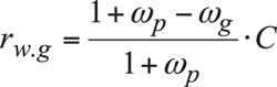
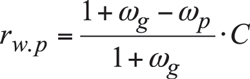
The distances between the apexes Ag and Apa, as well as between the apexes Ap and Apa are labeled as rw.g and rw.p , respectively. It is shown [2] that the radii rw.g and rw.p can be expressed in terms of parameters of the kinematics of the CA-gear pair:
 (1)
(1)
 (2)
(2)
The radii rw.g and rw.p are signed values. Both of them are positive for an external gear pair, and the radius rw.g is negative in a case of internal gearing*.
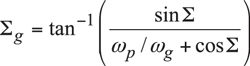
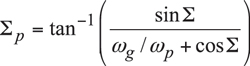
It is convenient to apply the rotation vectors ωg, ωp, and ωpl at the points Ag, Ap, and Apa of intersection of the center-line,CL , with the axis of rotation of the gear, Og, of the pinion, Op, and the axis of the instant rotation, Pln. Once the rotation vectors ωg, ωp, and ωpl are constructed, then one can proceed with the calculation of the gear and the pinion angles Σg and Σp, respectively. By definition, these angles are equal to Σg=(ωpl, ωg) and Σp,[ Σ=(ωpl, ωp, respectively. The angles Σg and Σp can be xpressed in terms of the parameters of the kinematics of CA-gearing [2]:
 (3)
(3)
 (4)
(4)
In a case of IA-gearing, the angles Σg and Σp are equal to the corresponding pitch cone angles, Γ and Γ, of the gear and the pinion. In a more general case of CA-gearing, the angles Σg and Σp can be used for the calculation of the cone angles for the cones that locally (within the face width) approximate the pitch surfaces of the gear and the pinion that in the case under consideration are shaped in the form of one-sheet-hyperboloids of revolution.

The rotation vectors, ωg, ωp, and ωpl, are helpful for the constructing of the plane of action in a CA-gearing. The plane of action, PA, is a plane through the vector of instant rotation, ωpl (that is, a plane through the axis of instant rotation, Pln). The plane of action, PA, makes a transverse pressure angle, φt.ω, with a plane through the axis Pln perpendicular to the center-line, CL , as depicted in Figure 2. The plane of action, PA, is rotated, ωpa, about an axis,Οpa (not shown in Figure 2), that is a straight line through the apex, Αpa. The transverse pressure angle, φt.ω, complements to 90° the angle that make the center-line, CL , and the axis of rotation, Οpa, of the plane of action, PA.
The plane of action, PA, can be used to construct the base cone of the gear in a CA-gearing. For this purpose, consider the plane of action, PA, that is rotated about the gear axis of rotation,Og. The base cone of the gear is generated as the enveloping surface to consecutive positions of the plane of action, PA, in such the rotation. This immediately allows for an expression for the base cone angle of the gear, Γb:
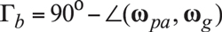 (5)
(5)
Similarly, the base cone of the pinion in a CA-gearing can be constructed. For this purpose, consider the plane of action, PA, that is rotated about the pinion axis of rotation, Οp. The base cone of the pinion is generated as the enveloping surface to consecutive positions of the plane of action, PA, in such the rotation. This immediately allows for an expression for the base cone angle of the pinion, Γb:
 (6)
(6)
When the gears rotate, the plane of action, PA, is unwrapping from the base cone of the driving member of the gear pair (commonly, this is the pinion), and is wrapping on the base cone of the driven member of the gear pair (obviously, this is the gear). No slippage is observed when the plane of action rolls over the base cones of the gear and the pinion in a CA-gearing.
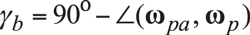
The rotation of the plane of action, ωpa, correlates to the rotations, ωg and ωp, of the gear and the pinion and to the base cone angles, Γb and Γb, in accordance to the ratio:
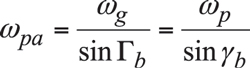 (7)
(7)
At this point, neither the gear tooth flank, G, nor the pinion tooth flank, P, are constructed yet. However, the gear designer is free to select a desired line of contact between the tooth flanks of the gear and the pinion.
The desired line of contact, LC between the tooth flank of the gear, G, and the tooth flank of the pinion, P, is a planar curve that is entirely located within the plane of action, PA. There is a certain freedom in selecting the geometry of the desired line of contact. As an example, consider a desired line of contact, LCi, that is shaped in the form of an arc of a circle of a radius RLC as illustrated in Fig. 3. An arbitrary point mi is chosen within the line of contact, LCi. The point mi is at a distance Rm from the plane of action apex, Apa.

An adjacent desired line of contact, LCi+1 (that is, the line of contact for the neighboring pair of teeth of the gear and the pinion in a CA-gearing), is located within the plane of action, PA, at an angle φb.op in relation to the desired line of contact, LCi. The angle φb.op is referred to as the operating base pitch. For a specified CA-gear pair, the operating base pitch is of constant value for all points within the desired line of contact between the tooth flank of the gear, G, and the tooth flank of the pinion, P (that is, φb.op=const) regardless of the distance, Rm, of a point mi from the apex Apa.
For a specified CA-gear pair, three design parameters:
• the operating base pitch, φb.op,
• the gear base pitch, φb.g, and
• the pinion base pitch, φb.p,
must be equal to one another:
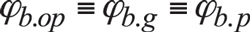 (8)
(8)
Any and all gearings must meet the requirement specified by Eq. (8).
In cases of ideal gearing, that is, when no axis misalignment is taken into consideration, all three base pitches, φb.op, φb.g, and φb.p, are of constant value.
The operating base helix angle, ψb.op, is measured between the radius to a point of interest, mi, and the tangential line to the desired line of contact at that same point, mi. At a specified distance, Rm, the operating base helix angle is equal at all the points mi, mi+1 and so on. However, the operating base helix angle, ψb.op, may vary as a function of the distance Rm.
The field of action (or the zone of action, in other terminology) is a portion of the plane of action, PA, that is between two circular arcs of the radii rpa and r1.pa (Figure 3), and that is cut by the outside surfaces of the gear and of the mating pinion. The angle Φpa spans over the field of action, FA. The design parameters of the field of action are used in the approach under consideration for the calculation of contact ratio in CA-gearing. Without going into details of the calculation of contact ratio, let’s just mention that in a simple case of straight bevel gearing, the transverse contact ratio, mp (and the total contact ratio as well), equals to the ratio:
 (9)
(9)
The discussed in this paper design parameters in aCA-gearing are referred to as the principal design parameters of the gear pair. Calculation of the remaining design parameters is a routine procedure known to most of gear experts in the field (see Table 11.2 on page 382 in [2]). For this purpose, an additional plane, that is, the pitch plane of the gear pair needs to be introduced. Tooth thickness, space width, backlash are specified in the pitch plane, PP, of the gear pair. The pitch plane is a plane through the apex of the plane of action, Apa, perpendicular to the center-lineCL, (Figure 4).
Methods of cutting gears for gear pairs with non-parallel axes of rotation of the gear and the pinion are summarized by the author [3].
Conclusion
The principal features of designing of gears for gear pairs with non-intersecting axes of rotation, that is, for CA-and LA-gearing are discussed in the paper. The novel concepts of:
• The plane of action, PA
• The base cones
• The operating base pitch, operating base pitch of the gear and pinion
• Base helix angle are introduced.
These concepts are not covered either by AGMA standards or by other national and international standards on gearing with non-intersecting axes of rotation.
Definitions to the newly introduced design parameters in a CA-gearing are given. Formulas for the calculation of the principal design parameters of gearing with non-parallel axes of rotations are provided.
References
[1] Radzevich, S.P., Dudley’s Handbook of Practical Gear Design and Manufacture, CRC Press, Boca Raton, Florida, 2012, 878 pages.
[2] Radzevich, S.P., Theory of Gearing: Kinematics, Geometry, and Synthesis, CRC Press, Boca Raton, Florida, 2012, 743 pages.
[3] Radzevich, S.P., Gear Cutting Tools: Fundamentals of Design and Computation, CRC Press, Boca Raton, Florida, 2010, 786 pages.


