


Introduction
As the growth of wind energy continues, the average size and capacity of wind turbine generators is also increasing. This size increase pushes designs and materials to new limits, potentially increasing the cost of operation; in particular the cost of repairs, downtime and unscheduled maintenance.
Wind turbine gearboxes are typically designed and certified by the wind industry to a minimum bearing L10 life of 20 years, or 175,000 hours. However, bearing and gear replacements are happening as early as in the first-to-second years of service. If the repair event requires a crane, the costs could be significant. Most utility customers do not calculate more than one major overhaul in the turbine’s 20-year life. This results in a difficult financial position when the overhaul occurs in the early years. In addition, if the replacement does not improve the performance, the problem can be compounded over the years of service and leave the end customer with excessive operation expenses.
Observations of Gearbox Bearing Damage Modes
Two types of early bearing damage are typically observed with wind-turbine gearbox failures: 1) micropitting and/or scuffing related to tribological issues; and 2) white-etch cracking (WEC) and/or axial cracking mainly related to metallurgical issues in severe application events. The scope of this document is to further understand WEC and axial cracking and discuss possible remedies for these damage modes. The micropitting/wear issues are covered under a separate document titled, “Life Limited Wear of Wind Turbine Gearbox Bearings.”
Our knowledge of bearings damaged due to WEC and axial cracking includes details on the following characteristics:
• Most of the axial cracking problems are generic in nature and not specific to a single manufacturer or turbine model
• Axial cracking is found in applications experiencing high transient loads
• Axial cracking occurs mainly on high speed and intermediate speed shafts; some planet positions have also been observed
• Axial cracking occurs predominantly on the inner race
• Axial cracking is most predominate in cylindrical and spherical roller bearings and less frequent in through-hardened tapered roller bearings
Examples of white-etch cracking and axial cracking of a cylindrical roller bearing from the high-speed output shaft of a wind-turbine gearbox are shown in Figures 1, Figure 2, and Figure 3. Axial cracks can be separating cracks (Figure 2), such that they propagate from race surface to bore surface, or non-separating (Figure 3), such that propagation terminates within the wall section. The variation in circumferential spacing of these cracks suggests that a single event did not result in the initiation, but rather, cracks were initiated and allowed to propagate under repeated application situations.
The location of crack initiation and magnitude of crack propagation depends on the location of the overload, frequency of the overloads and the magnitude of the normal operating conditions, as well as the material properties of the rings. However, in order to initiate and propagate an axial-ring crack, significant tensile stresses in the circumferential direction must be present.
Application Loads/Stresses
Bearings for a wind-turbine gearbox are usually designed for nominal stress loads while accounting for less frequent maximum power ratings. However, large transient events at the time of the generator/grid engagement result in torque levels in excess of that for maximum rated power, in both the negative and positive directions. In addition, there are transient torque peaks when the brake stops the system.
For example, Robinski & Smurthwaite (2010) have measured that a premature engagement of the generator to the grid forces the intermediate shaft of a 1.5MW rated gearbox to accelerate from 375 rpm to 422 rpm in a 2-second period, and a torque change from negative 800kNm to positive 430kNm occurs in less than 100 ms. During these events, high-contact stresses are experienced by the non-driven flanks of the gears, which can result in catastrophic tooth fracture. Torque reversals also generate an almost instantaneous change in the shaft loading direction. For example, in the generator/ grid engagement event described above, the intermediate shaft of the 1.5 MW-rated gearbox was measured to have a displacement greater than 600 μm, far greater than the radial clearance specified for the bearings (120 μm).
Most rolling-element bearings have loaded and unloaded zones in operation. In the loaded zones, rollers are well aligned and have high traction forces. On the other hand, the traction forces are much smaller in the unloaded zone. Consequently, the rollers are not as well aligned with the raceways and have higher slide/roll ratios. An instantaneous change in shaft loading from a torque reversal relocates the load zone of the bearing, and high contact stresses are applied to misaligned and sliding rollers. Because of the variability of wind conditions, torque reversals from generator engagement can happen thousands of times per year.
Mechanism/Damage Progression
Under normal or steady state operating conditions, the circumferential tensile stresses present are 1) hoop stresses due to press fits on the inner ring and 2) tensile stresses resulting from sliding stresses caused by bearing design and loss of roller traction force. However, this is usually not enough to initiate a crack. Additional stress is introduced in wind gearbox bearings due to the abnormal transient load conditions described above. So in order to initiate and propagate cracks in the radial direction, tensile stresses must exceed the material properties. However, if there are stress risers within the material, such as inclusions and hard second phases or pre-existing cracks, then the applied stress (nominal plus transient) does not have to exceed the material property for crack initiation and propagation; therefore, axial cracking may occur.
Axial cracking can initiate at the surface of the bearing race or at a depth below the surface. Surface or near surface initiation can occur either at an altered microstructure phase reported in literature as White Etching Areas (WEAs) or at embrittled grain boundaries found in high carbon steels, which is referred to in literature as Quench Embrittlement. Once the cracks have initiated, propagation will occur if the combined tensile stress in the circumferential direction exceeds that required for fatigue to occur. This critical stress is a material property and is a function of composition and microstructure. Sub-surface axial crack initiation can occur either at WEAs, pre-existing cracking that is associated with WEAs (reported in literature as White Etch Cracking), inclusions or other white etching phases known as a butterfly. The sub-surface initiation can occur at depths up to the depth to maximum Hertzian shear stress and the proximity to the surface is a function of sliding stresses.
Understanding the Phenomena of White Etched Area (WEA)
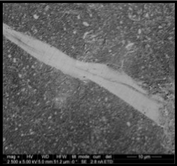
White etched areas are microstructural alterations that occur within the bearing microstructure over time due to application stresses. Figure 4 is a sample of WEA viewed with a SEM (Scanning Electron Microscope). The crack associated with this WEA is not visible in this image.
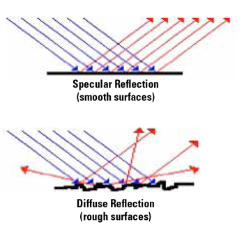
The name, WEA, describes the appearance of the particular microstructural feature, due to an inability of the structure to provide significant detail upon etching. The lack of etching detail results in a “white” appearance under common optical metallographic techniques. The white appearance is due to the specular reflection of smooth surfaces as shown in Figure 5.
The microstructure alteration mechanism starts with high transient loading in addition to nominal loading conditions. The combination loading results in localized plastic deformation and occurs as shear bands, not necessarily associated with inclusions or second phase particles. The shear bands are discrete locations of strain and are the areas where the cracks will eventually occur. When these shear bands combine, they form a network, which results in a crack network, since the cracks initiate within the altered microstructure (WEAs). The shear bands typically occur down to the depth of maximum shear stress, based on the loading, but the maximum stress will move towards the race surface because of the introduction of the sliding forces.
Within the shear bands (WEAs), a high density of dislocations (concentrated area of plastic deformation) is generated and moves to accommodate the strain. The energy associated with the dislocation density reverses the carbide precipitation by providing a driving force for the carbon to dissolve into a ferritic structure. It is this ferritic structure containing excess carbon that resists metallographic etching and appears white, as shown in Figure 4.
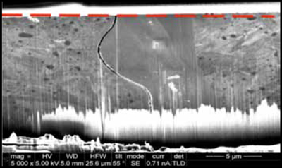
An SEM image is shown in Figure 6 of the white etch area previously shown in Figure 4. This image is depicting a cross section cut and polished perpendicular to the white etched area, as indicated by the red-dashed line. The black curved shape is a crack, the featureless, gray region in the center is the WEA, and the material on the left and right with the darker features is the original bearing steel microstructure. It appears that the shear band is formed in one transient cycle and then subsequent transient cycles or normal loading cycles alter the microstructure resulting in the white etching, featureless structure. The cracks will form and then follow the WEA; at which point the cracks will grow larger and result in axial cracks or spalling (white etch cracking).
Once initiated, the axial cracks will propagate via fatigue in the radial direction as well as the axial direction. If the axial cracks initiate below the surface, then fatigue will occur not only towards the bore of the ring, but also towards the race surface. Once the crack intensity of the propagating crack exceeds the fracture toughness of the material rapid fracture will occur. As crack propagation occurs by rapid fracture, the combined application tensile stresses driving the crack are decreasing. The combination of these application tensile stresses, ring thickness and material properties will determine if the axial cracking is separating or non-separating.
Separating and non-separating axial cracks may result in the initiation of surface fatigue damage and eventual race spalling. However, in addition to surface fatigue damage, separating axial cracks will result in the loss of press fit of the inner ring on the shaft and may cause motion of the inner ring on the shaft and additional bearing/gearbox damage.
Discussion
Axial cracking and white etch cracking occur where the application is generating a combination of nominal and transient loading. When these stress levels exceed the yield strength of the material, a significant portion of this transient load will be accommodated plastically, resulting in an altered microstructure of localized plastic deformation, known as white etched area. Cracks may initiate from this altered microstructure and propagate, either leading to race spalling or axial cracking.
Recommendation
Even though wind-turbine designs attempt to account for varying application conditions, transient loading conditions will continue to exist. As described above, the transient load conditions result in torque reversals, excessive pressure spikes, and large shaft deflections, which in turn cause increased bearing clearance, rolling element skidding and changes in load zones. Therefore, to improve gearbox reliability and reduce the occurrence of axial cracking and white etch cracking, the following recommendations are offered.
• Improved bearing designs with limited or no radial clearance, such as a tapered roller bearing, should be used to reduce skidding and associated surface tension while also limiting roller skewing.
• For intermediate high speed shaft (IHSS) and high speed shaft (HSS) applications, incorporate bearing designs that use carburized races (especially press fitted, rotating inner races.) Carburizing improves compressive residual stresses, case microstructure and provides a more fracture resistant core material all of which may resist axial cracking initiation and propagation.
– All carburized microstructures are not created equally. The Timken carburizing process and subsequent heat treatments are unique and may produce a more robust microstructure relative to WEC damage modes.
• For designs where radial clearance is necessary, such as cylindrical roller bearings, black oxide (BO) applied to all rings and rollers are becoming more common. However, since BO is a sacrificial surface treatment, not a coating, Timken continues to evaluate technologies with long-term protection against WEC over the life cycle of the gearbox, such as our Wear Resistant bearings.
• Bearings manufactured from high quality, clean bearing steel, such as Timken bearings, inherently exhibit fewer potential sites for crack initiation and tend to show less potential for axial cracking. Inclusion initiated cracking has been observed relative to wind energy gearbox, inner-ring axial cracking. The use of bearings manufactured from high quality steels should be used for these challenging wind applications.


