


By Dr. Abdullah Akpolat, Dr. Nihat Yildirim, Burak Sahin, Omer Yildirim, Bulent Karatas, and Fatih Erdogan
Tooth root fillet is the maximum bending stress concentration region during a torque transmission via gear pairs. Increase in gear root fillet radius due to a larger cutter tip radius provides a smoother transition from involute to root via a larger trochoid and increases root critical section thickness and moment of inertia against bending of tooth. Therefore, gear tooth root fillet has an important effect on gear tooth root bending stress. Fillet radius at critical section of gear tooth root, on the other hand, is mainly affected by the tip radius of the cutting tool. It is generally defined in terms of normal module and is called as coefficient of cutter tip radius. In the present work, the effect of symmetric and asymmetric cutter tip radii on root stress is studied by keeping all other gear parameters constant. First, symmetric (the same) coefficient of cutter tip radii for both drive and coast sides (as given in literature) are used, then asymmetric (different) cutter tip radii coefficients for two sides (for both drive and coast sides) of gear tooth profile are used to benefit from larger radii of curvature for a reduced bending stress on drive or tensile side of the flank. With reference to condition generated by standard symmetric cutter tip radii, almost 10-11 percent reduction in bending stress is obtained by using asymmetric cutter tip radii coefficients for two sides of gear tooth profile with standard center distance and no tooth interference.
1: Introduction
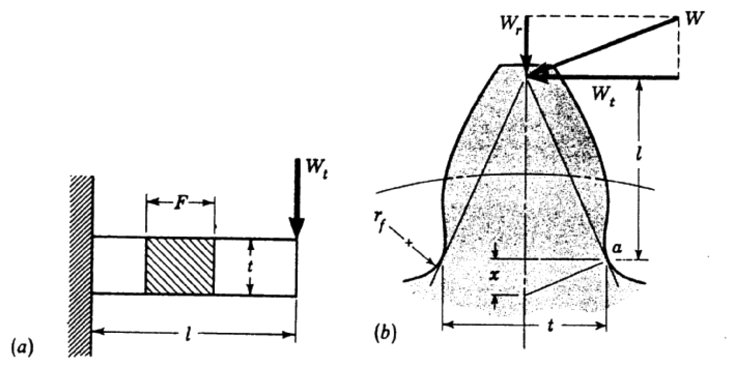
Gears under torque mainly experience two kinds of stress: contact stress at gear tooth surface and bending stress at tooth root during operation. Gear tooth surface durability relates to the ability to resist pitting and scuffing under contact stress; gear tooth strength relates to the ability to resist tooth crack and breakage under bending stress. Wilfred Lewis introduced an equation for estimating the bending stress in gear teeth based on the well-known bending equation in beams (Figure 1). Equation 1, announced in 1892, still remains the basis for most gear tooth bending design today, with many factors, including tooth form factor and others, added to this basic equation later [1].
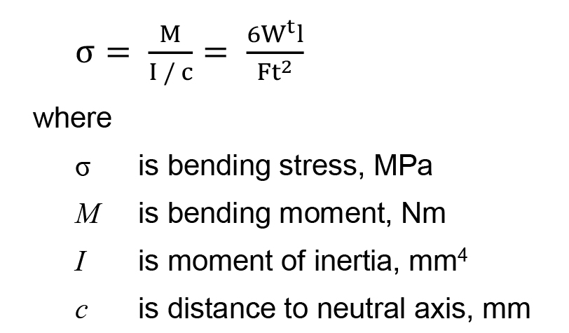
Referring to Figure 1, it is assumed that the maximum bending stress in a gear tooth occurs at point “a,” tensile stress loaded side of the tooth [1]. Moment of inertia of critical section is very essential for gear performance in terms of bending stress (Equation 1). Root critical section thickness, “t,” at point a, is taken into consideration for calculation of inertia and tooth root bending stress.
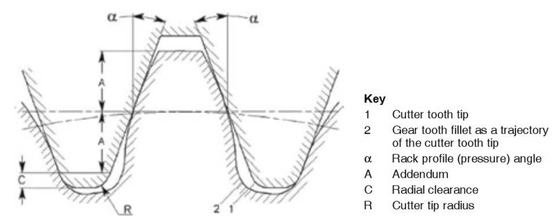
A gear tooth profile usually consists of two separate curves, namely involute and fillet curves. Gear profiles including involute and fillet curves are the result of gear manufacturing processes. The most widely used gear manufacturing processes are based on generating principle [3] as observed in rack cutter (MAAG), pinion cutter (Fellows shaping) and hob cutter cases (despite the fact that form cutters are also used rarely). All these generating type cutters have certain cutting profile parameters, and cutter tip (Figure 2) radius is the most important one to produce root profile (fillet) of the generated gear tooth [4] because gear tooth fillet profile is typically determined by the generating cutting tool (rack or gear hob or shaper cutter) tip trajectory, also called the trochoid [4].
Therefore, fillet radius (radius of curvature) at tooth root (produced by one of the generating methods) is of a variable nature [5] and varies from point to point. It is not only the position in the tooth root, but also the cutter tip radius (value or coefficient) does affect the value of radius of curvature in fillet region.

Considering only the rack cutter (which represents also the hob cutter) for manufacturing gears with involute tooth, the tooth profile for such a rack becomes a straight line, as seen in Figure 3 [6].
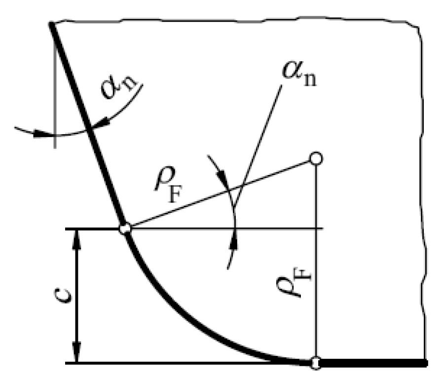
The parameters of the basic tooth rack (Figure 3) are standardized in DIN 867 [7] and ISO 53 [8]. This is a rack cutter (inverse of the rack tooth and having infinite diameter) with straight tooth profiles symmetrical about the midline of the tooth. The theoretical form and dimensions of the involute tooth and gear (generated by this rack cutter) are determined by that standard rack tooth [6]. The bottom clearance, c as depicted in Figure 4 [6], depends on the requirements to be met by the gear and gear manufacturing facilities. This limits the fillet radius ρF = ρ*Fmn of the basic rack tooth profile for the cylindrical gear and thus the tip rounding radius of the tool basic rack tooth profile.
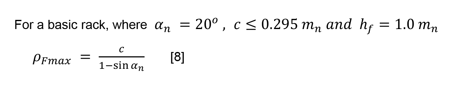
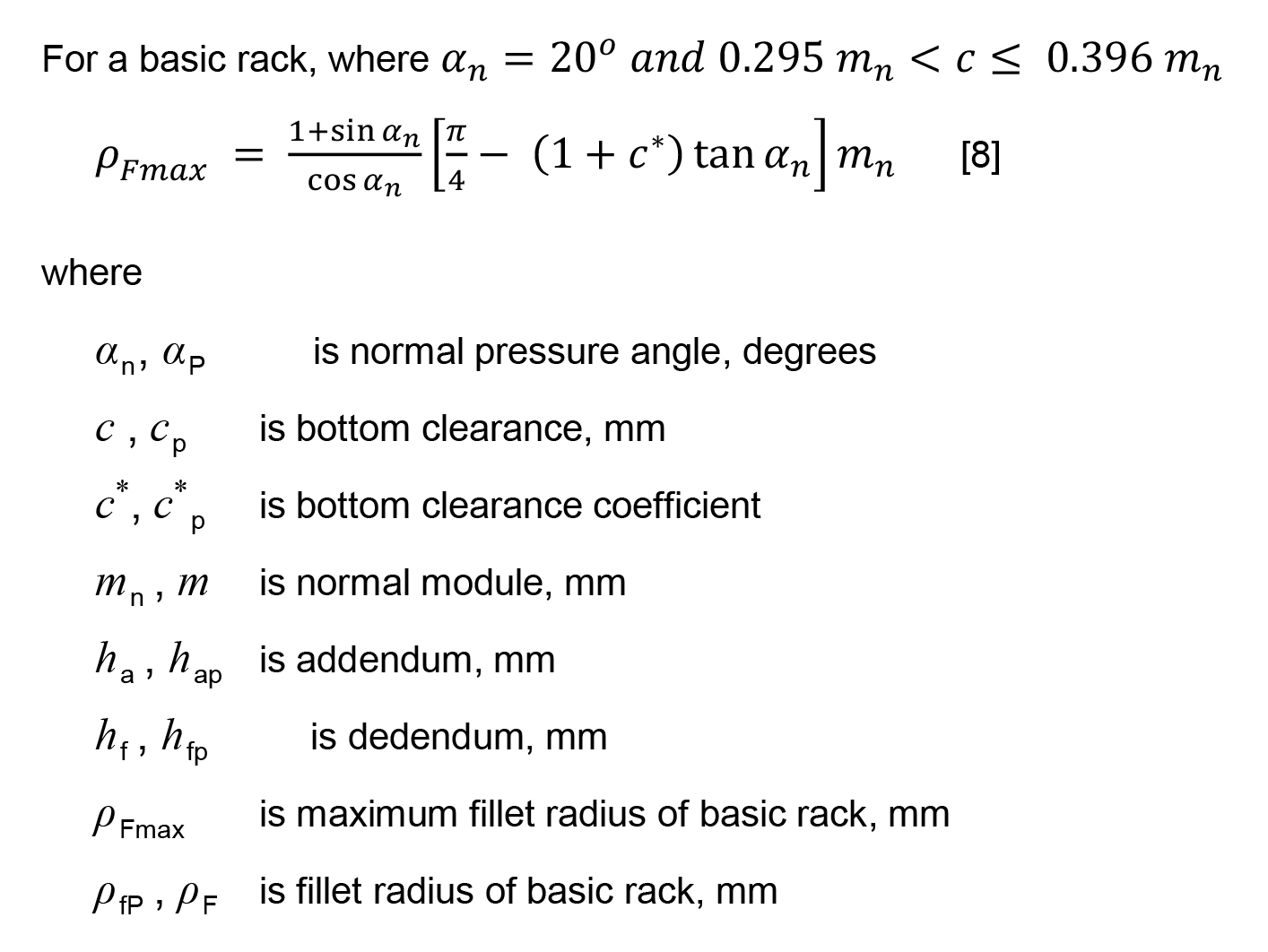
Custom gear teeth are generally produced with symmetric fillet profiles on both sides (drive and coast) of gear tooth profile by using the symmetric rack cutter tips. A limitation for maximum fillet (cutter tip) radius of such symmetric basic rack is stated in both standards DIN 867 [7] and ISO 53:1998(E) [8]. In ISO 53:1998(E) it is given as below:
There is a similar relationship, stated by DIN 867 [7], between bottom clearance coefficient cp* and coefficient of fillet radius coefficient ρ*fp as shown in Figure 5 with a transition limit of 0.295 for bottom clearance coefficient, cp*. Standard basic rack proportions suggested by ISO 53 [8] are presented in Table 1. Other basic rack tooth profiles for different application alternatives suggested by ISO 53 [8] are given in Table 2. Type A, B, C and D are recommended for high torque transmission, normal service, and high precision gears transmitting high torque [8].
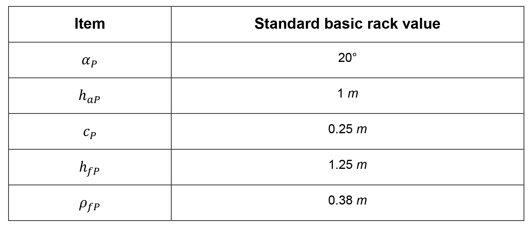
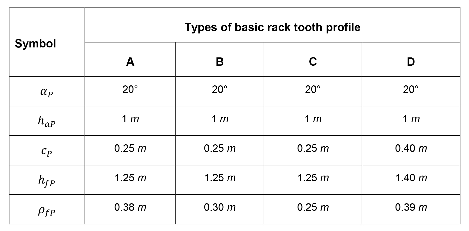
Table 1 and 2 show different standard basic rack proportions and symmetric fillet radii generally used for gear generating operations. The upper limits of coefficient of fillet radii of basic rack cutter (tool tip radius) seem to go up to a maximum value of 0.39 (depending on dedendum) although 0.25 and 0.30 are also suggested. The lower limit for that coefficient, although theoretically possible, physically is not zero, because a zero fillet radius (sharp corner) on the rack cutter tip may cause some manufacturing difficulties such as the risk of cutting tool tip fracture while cutting gears.
2: Literature
Some of the most recent literature studies about cutter tip and fillet geometries and resulting bending stress conditions are given below.
Kapelevich et al. [4] presented a paper about a fillet profile optimization technique for gears with symmetric and asymmetric teeth based on FEA and a random search method. It allows achieving substantial bending stress reduction in comparison with traditionally designed gears. This bending stress reduction can be traded for higher load capacity, longer lifetime, lower noise and vibration, and cost reduction. Bending stress values are calculated and presented for different fillet profiles like trochoid, circular, and optimized fillet profile. Bending stress reduction with 10–20 percent was provided by optimizing fillet in comparison with traditionally defined root fillet profiles.
Despite the fact that optimization of tooth root fillet provides a certain reduction in bending stress, manufacturing of these optimized fillets will not be possible by conventional generating processes like rack, pinion, and hob cutters and will require non-conventional gear cutting processes. This will then add extra cost to gear cutting in terms of special tooling, and increased machining time.
Zhao et al. [11] used a novel curve (quadratic rational Bezier curve) to describe the cutter tip. The gear tooth finite element model was constructed by APDL in the ANSYS software. With the maximum bending stress (Von Misses stress) as the objective function, sub-problem and first-order optimization methods in ANSYS were used to optimize the cutter tip. The study reveals that the relationship between the design variable and tooth root bending stress is nonlinear, and the gear cut by the optimized cutter exhibits lower bending stress than the gear cut by a standard cutting tool.
Contrary to Kapelevich et al. [4], this study focuses on optimization of cutting tool tip rather than the optimization of tooth root/fillet profile. These two papers, Kapelevich et al. [4] and Zhao et al. [11] are somehow complementary, for one is optimizing the root/fillet profile itself and the other is optimizing the tool tip which cuts a specified root/fillet profile. However, such cutting tools intended to be manufactured by CNC milling or wire cutting are of special shape and may add extra cost due to special tooling.
Hebbal et al. [12] investigated the stress at the gear tooth profile by replacing the conventional trochoid fillet by polynomial curves. The circular root fillet profile is constructed by drawing an arc tangent to working profiles and root circle, and this arc is taken as reference root fillet to generate alternative root fillet profile. The arc is divided into six segments. New fillet profiles are constructed by displacing the middle points radially using different relations and keeping the end points fixed. The improved root fillet profiles resulted into reduction of bending stress by 9 to 12 percent. Results presented are based on two-dimensional finite element analyses (FEA).
A circular root fillet profile is used instead of trochoid to decrease bending stress. It is more advantageous in terms of bending stress level, but manufacturing difficulties are another concern to decide about root form. It is more expensive and more time consuming compared to trochoid profile. Fillet forms are symmetric on both sides of the tooth and not making use of asymmetric fillet form advantage.
Ristic´ et al. [13] gave attention to analysis on impact of gear tooth fillet radius at the critical cross section on stress value and distribution. Their study is focused on finding the optimal fillet tooth root radius to minimize the tooth root stress intensity. Results achieved by application of numerical methods — finite element method (FEM) and real working conditions simulation -— are presented for Von Mises and normal stresses as well as charts against different values of tooth root fillet radius in two cases: with one tooth root fillet radius and with two fillet radii (“two-level approach” in a root).
Two root fillet radii are recommended to apply for one (tensile) side of the gear tooth profile in Ristic´ et al. [13]. This application will remain limited in practice, and it does not always produce low stresses as stated in the paper, due to manufacturing difficulties about obtaining the same root profile for gear pairs which will work together.
Spitas et al. [14] prepared a paper performing a parametric investigation of the combined effect of the cutter tip radius and the dedendum on the clearance and the resulting tooth bending strength using analytical calculations, computerized generation and finite element simulations to determine the exact tooth geometry in search of stronger tooth forms. Non-dimensional modeling is used to obtain results applicable to entire gear families. The intrinsic geometry of the cutting process always results in a non-involute root profile (the trochoid), which is even more pronounced in the case of using a rounded cutter tip in order to increase the strength of the cutting edge. Larger tip radii produce stronger tooth fillets, potentially increasing the bending strength, but reducing the involute part of the tooth.
Spitas et al. [14] states new limitations different from ISO 53 [6] and DIN 867 [7] for cutter tip radius in terms of dedendum and bottom clearance. Symmetric cutter tip radius coefficient can be applied up to 0.47 depending on clearance and/or dedendum instead of 0.38 given in standards.
Alipiev [15] has also studied cutter tip radii effects but specifically for undercut-small number of teeth applications like pump gears with 4 to 10 teeth. He has derived specific relations for realizing the continuity of motion (Realized Potential Method) for the geometric design of gears with a very small number of teeth while avoiding undercut.
In the following sections of the study, new limitations stated by Spitas et al. [14] for symmetric fillet are taken into consideration, and further limitations for asymmetric fillets are discussed. Some case studies are performed using FEA tools and in-house prepared software developed by Şahin B. [9] and Şahin B. et al. [10] and bending stress results are evaluated.
3: Rack Cutter ReDesign
Based on the literature review and the bending stress theory discussed above, it is rather clear that the fillet geometry of tooth profile and eventually the cutter tip geometry of the cutting tool have a potential to effectively reduce the tooth bending stress. Non-standard (circular, optimized, spline, two fillets etc.) fillet geometries are usually more expensive and more difficult to manufacture by using conventional generation processes. Similarly, non-standard cutter geometries (Bezier like cutting tips etc.) require special tooling and may cause unexpected fillet profiles if the cutting tool designer is not well experienced.
For years, involute gear tooth including fillet with trochoid form has been successfully manufactured by using conventional rack and hob type cutting tools with circular tool tip having a radius of:

where ρ*F may vary between two (lower and upper) limits depending on dedendum and clearance values. Long experience gathered over the years has also perfected the design of both rack and hob type cutters for mass production of such gears. However, most cutters were designed as symmetric regarding the radii of tool tip on drive and coast sides, as seen in Spitas et al. [14] and international gear standards.
To our limited knowledge, no cutter design, so far, with asymmetric tool tip radii has been suggested/noted by researchers and standards to effectively reduce the bending stress in tooth root.
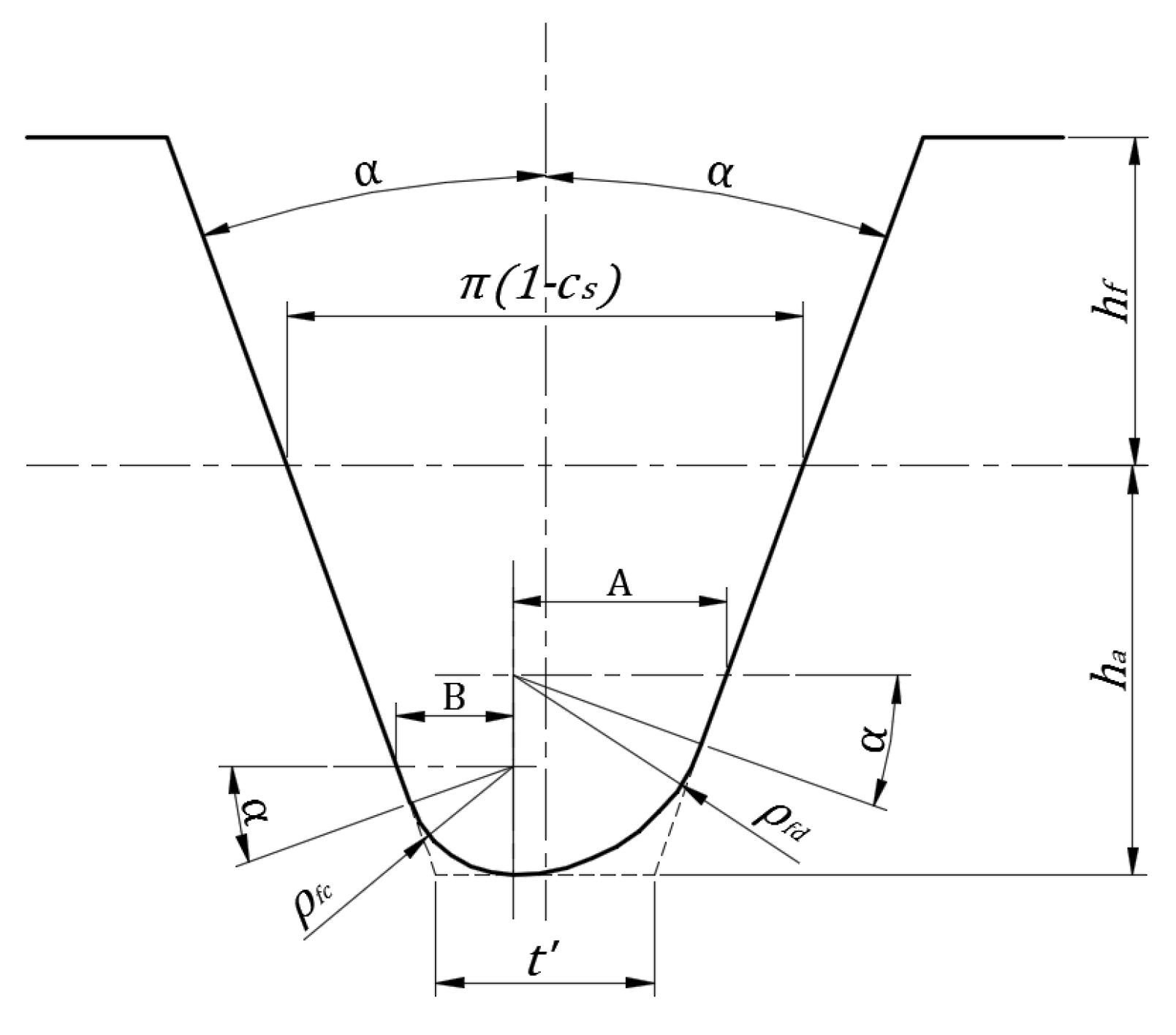
In this paper, effectiveness of asymmetric cutter tip radii on tooth root bending stress is studied. Limitations for asymmetric cutter tip radii are stated in Figure 6, and related equations are derived in the following section.
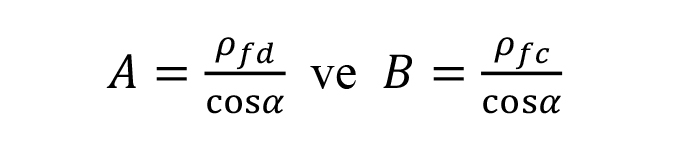
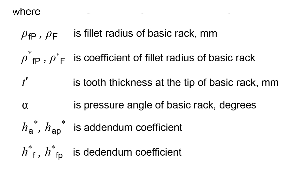
An asymmetric cutter tip radius of basic rack is given in Figure 6 where ρ*fd and ρ*fc are the coefficients of cutter tip radii for drive and coast sides respectively. From this figure, for a standard tooth with zero backlash, (tooth thickness coefficient, cs =0.5) we can write that:


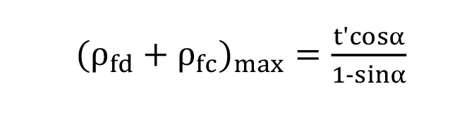
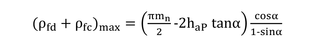
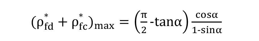
 Equations 11 and 12 provide the maximum value for summation of cutter tip radii and radii coefficients respectively for drive and coast side profiles. Equation 12 is a general one for both symmetric and asymmetric fillets (cutter tip radii) and can be compared with the symmetric ( ρ*fd = ρ*fc = ρ*f ) case studies provided in
Spitas et al. [14].
Equation 13, derived from Equation 12 for symmetric fillets (cutter tip radii), is used for cases below with:]
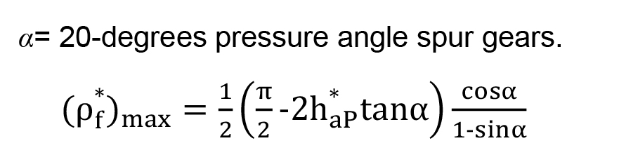
 For asymmetric fillet teeth with pressure angle of α = 20 degrees, similar case studies given in Spitas et al. [14] could be used to determine the upper limits of coefficient summations.
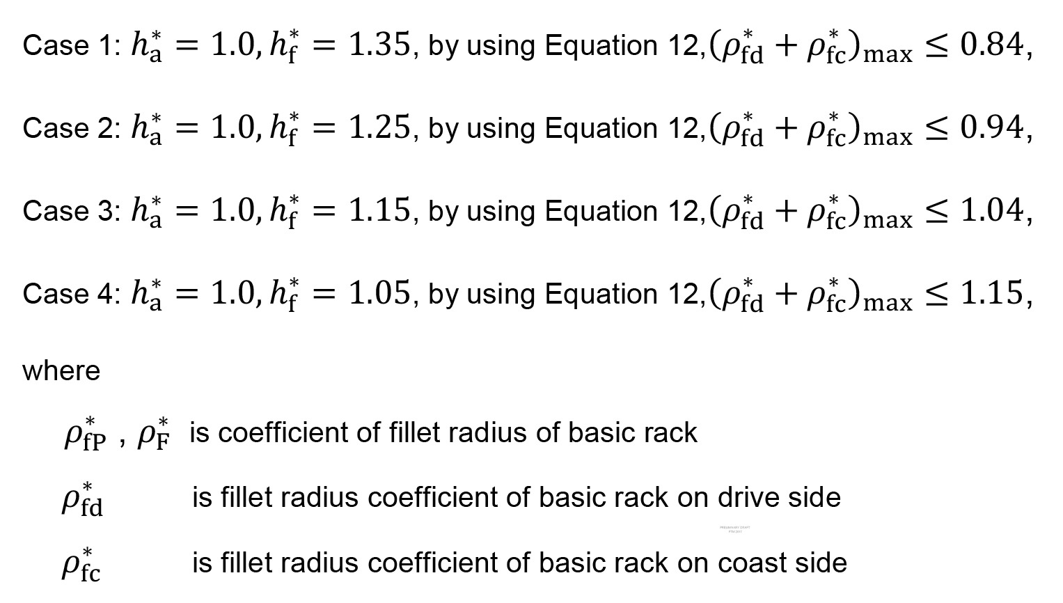 For each case of asymmetric fillet, ρ*fd and ρ*fc values could freely be chosen as long as the summation of the two coefficients, at maximum, satisfies Equation 12 and no interference occurs between mating teeth. In addition, the extreme condition of setting one of the parameters (ρ*fd or ρ*fc) to zero is not suggested since sharp corner cutters are not suitable for any metal cutting operations. For the standard case of 2, with h*a = 1.0, h*f =1.25, and (ρ*fd +ρ*fc)max = 0.94, the following options in Table 3 (and many more alternatives) are possible.

4: Case Studies of Symmetric and Asymmetric Cutter Tip Radii
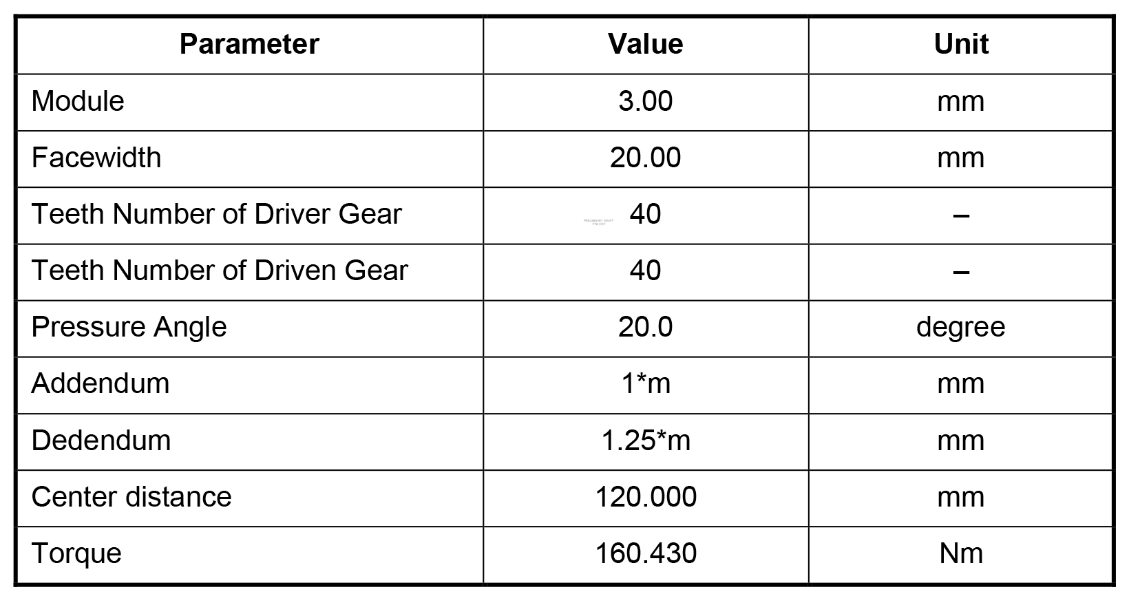
A work plan of bending stress analysis for both symmetric and asymmetric fillets is accomplished below to investigate the effectiveness of using different cutter tip radii. In the scope of this study, tooth root stress is calculated by using two methods: Finite Element Analysis (FEA) and in-house prepared software by Şahin B. [9] and Şahin B. et al. [10] based on the ISO 6336-3 standard [16]. Gear pair parameters to be used in analysis are presented in Table 4.
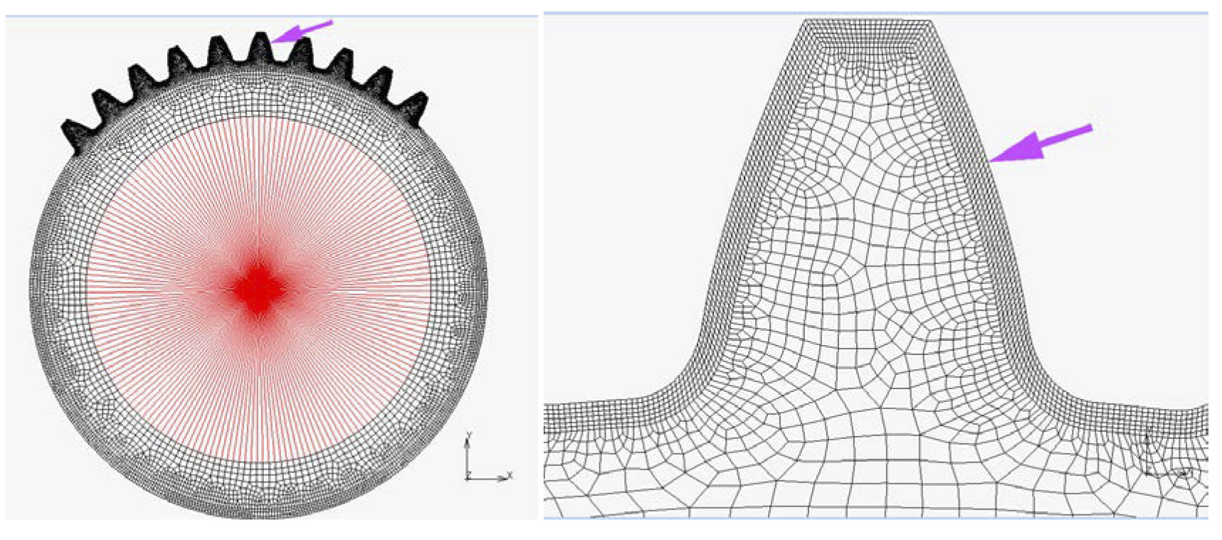
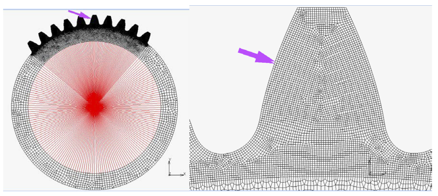
Finite element analysis MSC Software, MARC, is used to simulate the loading of different gears with consistent boundary conditions and loadings. Tooth load is applied at the highest point of single tooth contact (HPSTC) as pressure from the element edge, and gears are fixed inside the bore diameter as shown in Figure 7. Element types are quadratic eight-node and triangular six-node elements. Element size on the tooth surface contour is about 0.10 mm, and total numbers of elements are 24176 and nodes are 75019. Gear tooth geometry used in FEA modeling (including involute and trochoid) is constructed by using the well-known equations of meshing provided by [3].
4.1: Symmetric Fillet Cases
Symmetric fillet radii coefficients of basic racks, as used in many gear designs, are first applied to both drive and coast sides, as given in Table 5. Tooth root bending stresses calculated based on ISO 6336-3 [16] and FEM are presented in Table 5 and Figure 8. A sample FEM bending stress result is given in Figure 9.
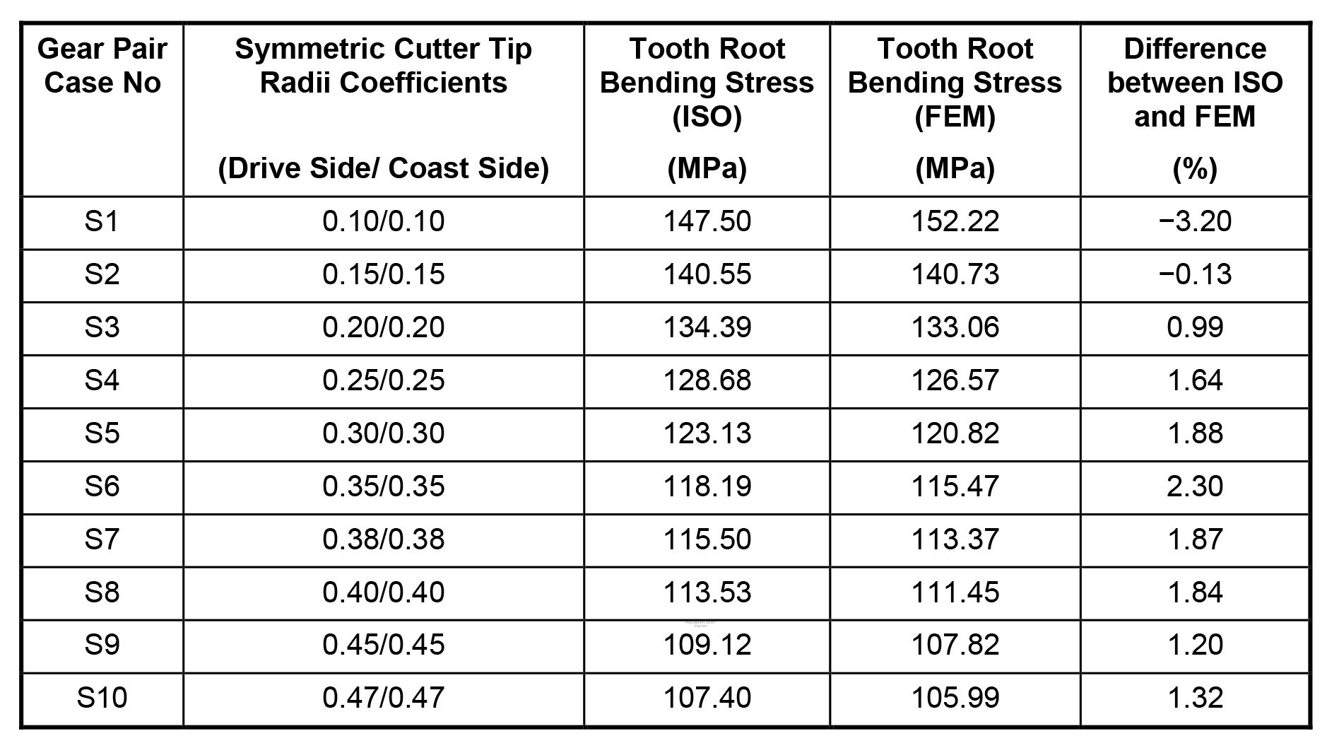
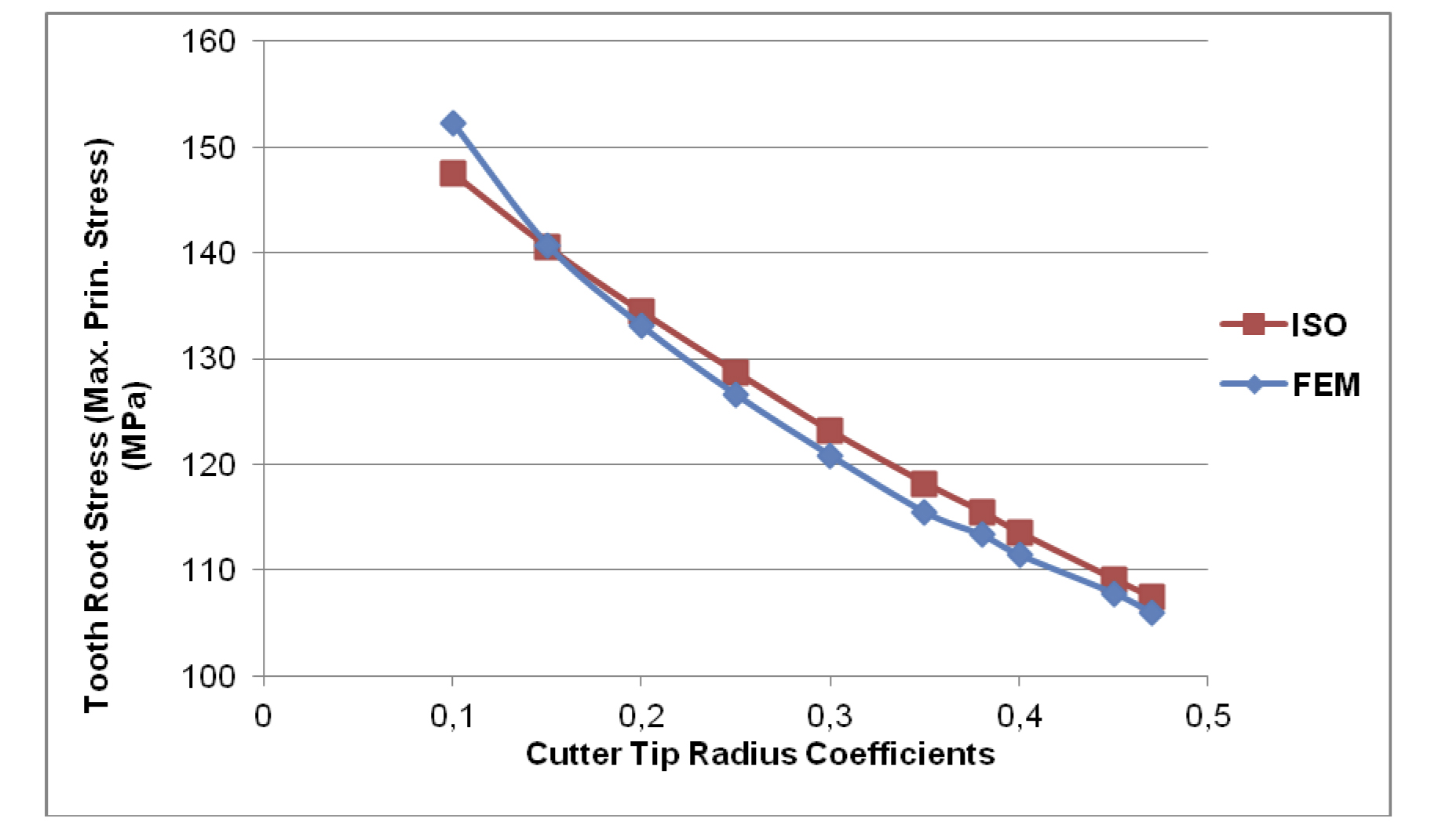
As clearly seen, the larger the cutter tip radii, the smaller the bending stress is. This is an inherent result of a thicker tooth at fillet (and shorter moment arm) at the critical section. Different from all the standards, the upper limit for the cutter tip radii coefficient of a symmetric fillet could be raised up to 0.47 (for Case 2 design) as already stated in Spitas et al. [14]. A cutter tip radii coefficient increase beyond 0.38, up to 0.47, helps decrease root stress an additional 6.5 percent. This is an extra potential for stronger gears carrying more torque/load.
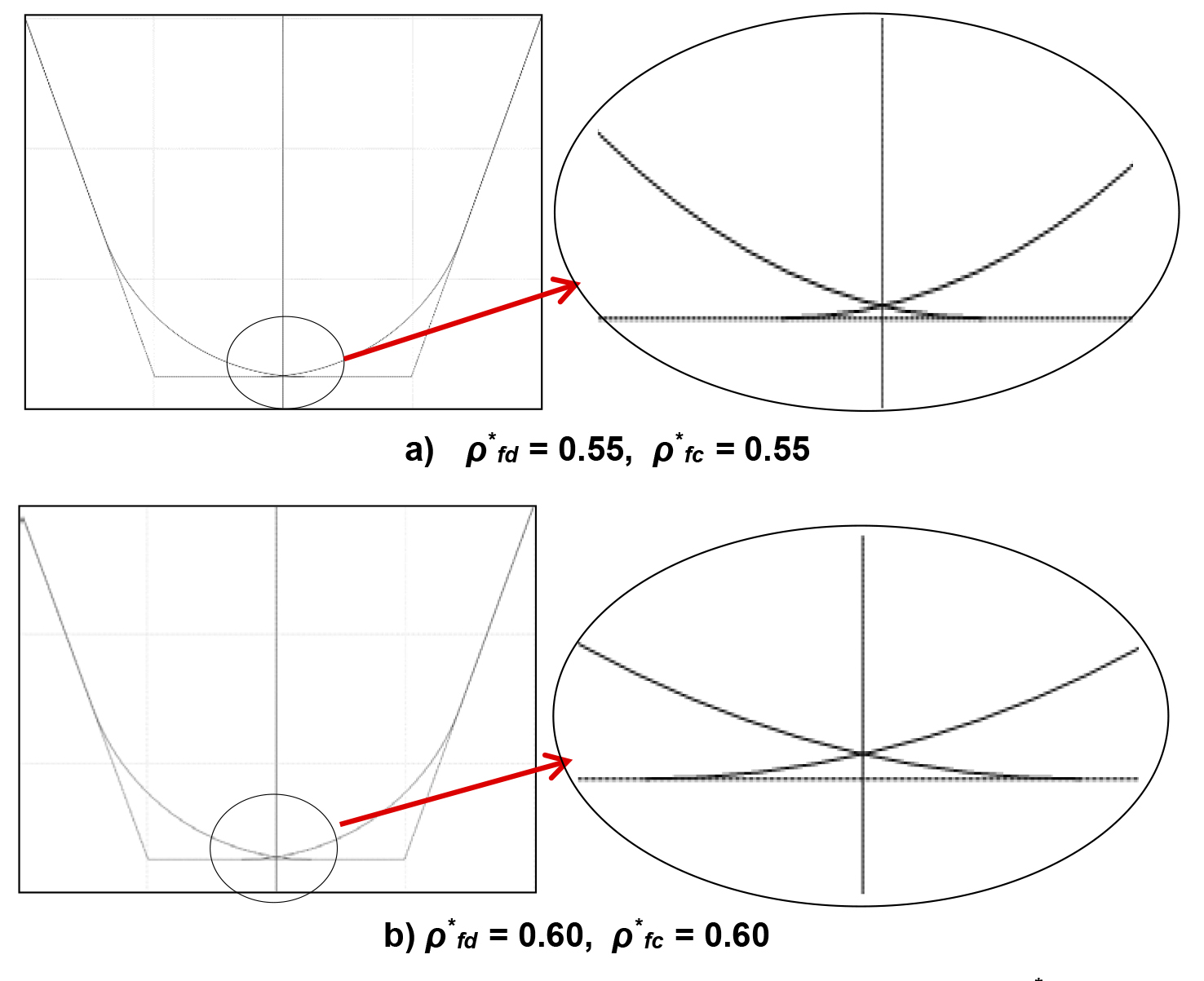
What happens if we want to further increase the tip radius of the cutter beyond the upper limit of 0.47. It is clear that a further increase in tip radius (of the symmetric cutter) will cause cutter geometry with reduced dedendum, hence a reduced clearance and a sharp midpoint at the cutting edge of the cutter tip, as shown in Figure 10. This, certainly, is not a suitable rack cutter tooth form and not a suitable tooth proportion.
4.2: Asymmetric Fillet Cases
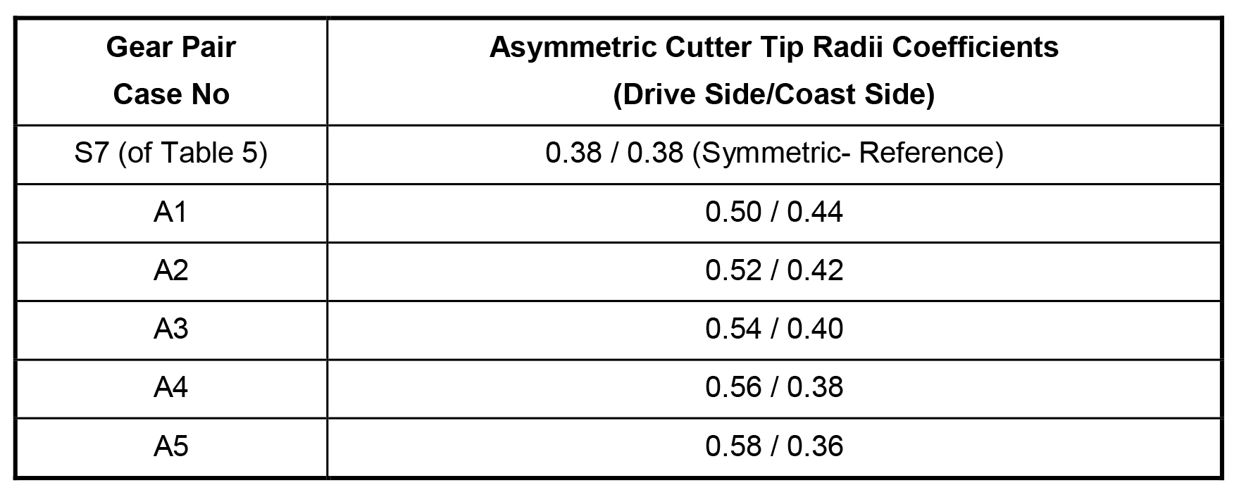
Using two different tip radii (with asymmetric form on coast and drive sides) and obeying Equations 11 and 12 will avoid both reduced dedendum/clearance and the sharp midpoint at the cutting edge of the cutter tip and will also help increase cutter tip radius with an increased thickness at tooth root. A list of likely asymmetric fillet cases is given in Table 6 for the gear pair of Table 4.
Drive side coefficients are purposefully selected as larger than coast side to reduce the bending stress on the drive side where tensile stress occurs. Just the opposite happens on coast side where compressive bending stress increases due to smaller coefficient; luckily, materials are stronger in compression than in tension. This condition, however, requires gears rotating only in one direction, which means asymmetric fillet designs are more suitable for one-way drive systems (like helicopter transmission gears). This is not a rare case, because most gear drive systems run over 90 percent of their life in one-way.
Assuming that the gear rotation is one-way only, gear teeth are designed based on asymmetric cutting tip radii for drive and coast sides, larger at the drive side. So, a maximum useful/usable tip radius of a basic rack cutter for the drive side can be selected more than the value suggested by ISO 53:1998(E), DIN 867, and similar standards, and even more than what is suggested as optimum in Spitas et al. [14]. These asymmetric cutter tip radius coefficients are applied for gears and checked graphically by using the home-prepared software for a geometrically safe operation of gear pairs without any undercut and interference. Case A5 (in Table 6) is checked for meshing interference in Figure 11a, and no interference is observed. Whereas another case of larger drive side coefficient with ρ*fd = 0.70, ρ*fc = 0.24 can be seen in Figure 11b with tooth tip interference.
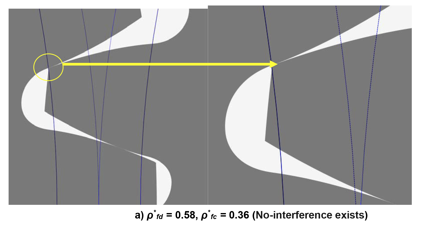
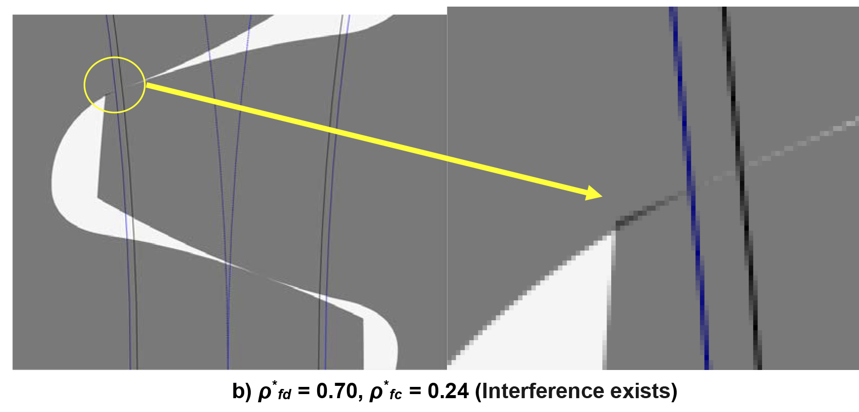
Any case with a drive side coefficient larger than 0.58 (for the gear pair in Table 4) creates/causes interference at the driven gear root (or tip of the driving tooth). Such interference is checked by controlling radii of the start of active profile (SAP) and intersection of involute and/or trochoid profiles (on the same tooth drive side).
Teeth manufactured/generated by asymmetric cutter tip radius coefficients for drive and coast sides are modeled in the MSC Software MARC to simulate the loading of different cases with consistent boundary conditions and loadings. Loads are applied from edge of elements at the highest point of single tooth contact (HPSTC) as pressure (creating the required tooth load and torque), and gears are fixed from the bore diameter as shown in Figure 12.
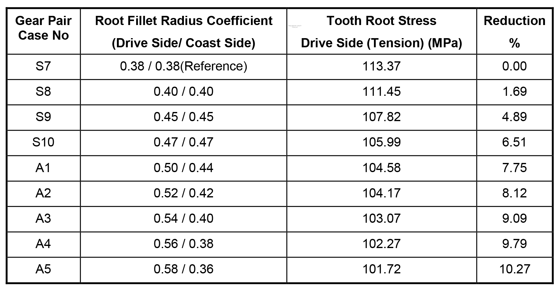
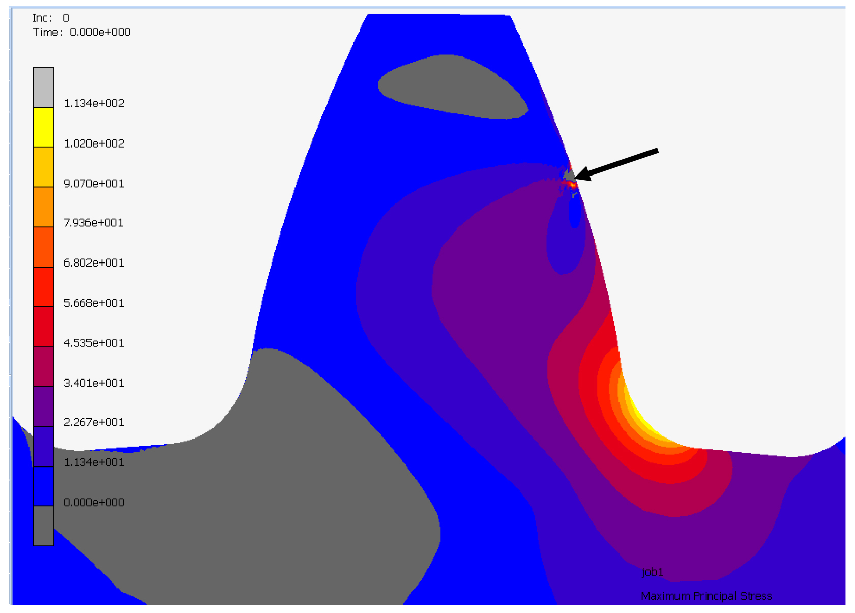
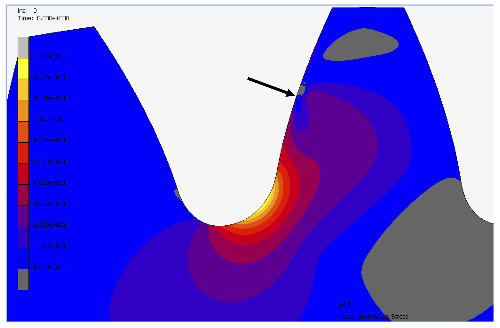
Stress values for cases of different asymmetric cutter tip radius coefficients (for drive sides) are determined by using FEM and are presented in Table 7 and Figure 13. FEM model results of a specific case (with coefficients 0.58/0.36) is given in Figure 14.
With the condition of “no interference” during meshing (and reference to case S7 of symmetric root fillet suggested by ISO 53:1998(E) with ρ*fd = ρ*fc = 0.38), almost 10.3 percent bending stress reduction is provided if asymmetric root fillet case of A5 with ρ*fd = 0.58 and ρ*fc = 0.36 is applied. Considering the small design change made to cutter geometry (modifying symmetric cutter tip radii to asymmetric, hence the resulting asymmetric trochoidal tooth fillets), the benefit of 10.3 percent reduction in bending stress is a considerable benefit resulting in either a longer service life under the same torque transmitted or an increased load/torque capacity with the same service life.

5: Results and Discussion
Theoretically, the gear tooth root does not get into contact, but it is the region of maximum bending stress concentration. Fillet region/geometry and fillet radius of gears have a significant effect on gear tooth root critical section thickness, hence on root stress. This, therefore, makes it very essential that fillet geometry is modified/controlled for decreasing bending stress and improving gear service life.
In the scope of this study, keeping all parameters constant except cutter tip radius coefficients, tooth root stress decrease is obtained:
By using increased symmetric cutter tip radius coefficients (the same tip radius) for both sides of the gear tooth profile, and;
By using “asymmetric cutter tip radius coefficients” (a larger fillet radius for the drive side and a smaller one for the coast side) with an improved gear tooth root profile and no tooth interference.
Standards ISO 53:1998(E) and DIN 867 state some limitations (usually a cutter tip radius of 0.38) for symmetric fillet radius of a basic rack model A. Based on FEM stress analysis, increasing symmetric the cutter tip radii coefficient beyond 0.38, up to 0.47, helps decrease root stress an additional 6.5 percent. This is an extra potential for stronger gears carrying more torque/load.
When applying “asymmetric cutter tip radius coefficients” of 0.58 and 0.36 (for drive and coast sides, respectively), a stress reduction of nearly 10 percent is obtained, with reference to symmetric condition of 0.38 / 0.38 coefficients as suggested in international standards. Reference to case of symmetric cutter with coefficients of 0.47 / 0.47, the same asymmetric cutter provided an extra 4 percent stress reduction. This additional stress reduction (of 10 percent and/or 4 percent) is likely to result in longer service life and/or increased load/torque capacity. Such fillet-modified gears, manufactured based on generation method, such as in conventional hob and rack type cutters, are also expected to be less expensive than gears with non-trochoid specific/special fillets.
The combined effect of asymmetry, both in root profile shape (asymmetric trochoid/root of this study) and tooth profile shape (asymmetric tooth) on the bending stress is the subject currently being analyzed for likely further reduction in gear tooth root stress.
References
- Budynas R. G., Nisbett J. G., 2006, Shigley’s Mechanical Engineering Design, McGraw-Hill, USA.
- Davis J. R., 2005, Gear Materials, Properties and Manufacture, ASM International, USA.
- Litvin Faydor L., 2004, Gear Geometry and Applied Theory, Cambridge University Press.
- Kapelevich A., Shekhtman Y., “Tooth Fillet Profile Optimization for Gears with Symmetric and Asymmetric Teeth,” AGMA Fall Technical Meeting, San Antonio, Texas, 11, 2008, 12-14.
- Colbourne J. R., 1987, The Geometry of Involute Gears, New Jersey, USA.
- Jelaska, D., 2012, Gears and Gear Drives, UK.
- DIN, 1986, “Basic rack tooth profiles,” DIN 867.
- ISO, 1998,“Cylindrical gears for general and heavy engineering-standard basic rack tooth profile” ISO 53:1998 (E).
- Sahin, B., 2015, “Development of user friendly interface software for design and analysis of parallel axes external gears including quasi-static transmission error calculations,” M.S. thesis, Mechanical Engineering Department, University of Gaziantep.
- Sahin, B., Akpolat, A., Yildirim, O., Uctu, O. and Ersoz, A., “Development of A User Friendly
Interface for Design and Analysis of Parallel Axes Gears Based on International Standards Including Quasi Static Transmission Error Curves,” International Gear Conference, Lyon, 2014.
- Zhao, X., Zhang, J., Lıu, H. and Wang, B., 2014, “Increasing Bending Strength in Spur Gears Using Shape Optimization of Cutting Tool Profile,” U.P.B. Sci. Bull., Series D, vol. 76.
- Hebbal, M. S., Ishwar, T. M., Rayannavar, P. and Prakash, K. H., 2014,“Reduction of Root Fillet Stress by Alternative Root Fillet Profile,” International Journal of Research in Engineering and Technology, vol.3.
- Ristic´, D. S. and Kramberger, J., 2014, “Gear Tooth Root Stress And Fillet Radii Dependence,” FME Transactions, Vol. 42.
- Spitas, C., Spitas V., Amani, A. and Rajabalinejad, M., 2014, “Parametric Investigation of the Combined Effect of Whole Deptha Cutter Tip Radius on The Bending Strength of 20◦ Involute Gear Teeth,” Acta Mech, 225, 361-371.
- Alipiev, O., 2011, “Geometric Design of Involute Spur Gear Drives with Symetric and Asymetric Teeth Using the Realized Potential Method,” Mechanism and Machine Theory, 46, 10-32.
- SO, 2006,“Calculation of Load Capacity of Spur and Helical Gears, Part 3: Calculation of Tooth Bending Strength,” ISO 6336-3:2006.
About the authors Dr. Abdullah Akpolat, Dr. Nihat Yildirim, Burak Sahin and Omer Yildirim are affiliated with Gaziantep University. Bulent Karatas is with BCS Metal Co., and Fatih Erdogan is with Ermakina Gear Industry. The authors extend special thanks to the TUSAŞ Rotary Wing Technology Center (RWTC) for support provided for this study. Copyright© 2017 American Gear Manufacturers Association, October 2017, ISBN: 978-1-55589-568-6. The statements and opinions contained herein are those of the author and should not be construed as an official action or opinion of the AGMA.
Printed with permission of the copyright holder, the American Gear Manufacturers Association, 1001 N. Fairfax Street, Suite 500, Alexandria, Virginia 22314. Statements presented in this paper are those of the authors and may not represent the position or opinion of the American Gear Manufacturers Association (AGMA). 17FTM06


