


In today’s online dating world, you are asked several pointed questions in order to determine your perfect match. Just like human relationships, gears work best when they are properly matched.
In order to find the proper style of gear for an application, the first consideration needs to be what gear type will fit with the shaft orientation of the system. The possibilities are:
- Parallel axes.
- Intersecting axes.
- Nonparallel and nonintersecting axes.
Once the determination of shaft orientation is made, the second decision involves the speed ratio requirements. Certain styles of gearing can provide high speed ratios, whereas others are limited to small ratios.
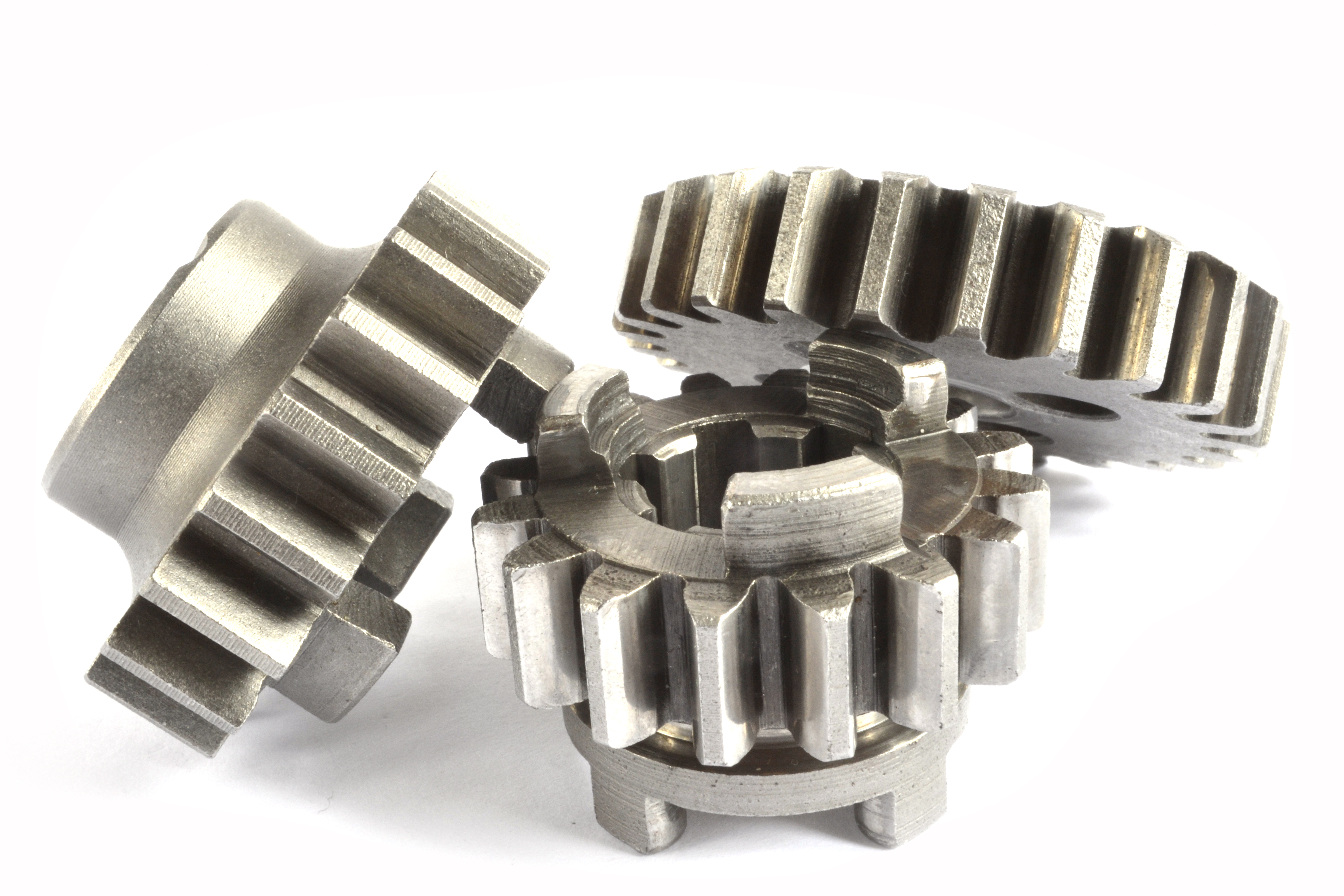
For parallel axes applications, the most common style of gear is the spur gear. This style of gear is cylindrical in design and has the teeth cut parallel to the axis of the bore. This is the most common style of gear and is quite versatile, as it can be mated with either another spur gear or with a gear rack. A great advantage of spur gears is that you can combine two gears of the same pitch and pressure angle regardless of the number of teeth on each gear. This allows for an infinite variety of fractional speed ratios. The limitation is that it becomes impractical to produce speed ratios greater than 10:1, as the pitch diameter of the larger gear typically becomes too large for the design envelope.
The gear rack is another parallel axis style of gear. The design of a gear rack is technically that of a spur gear that has an infinite pitch radius. A gear rack can mate with any spur gear that has the same pitch and pressure angle. They have the advantage of being able to be produced with finished ends, which permit racks to be butted end to end in order to form an infinite length of rack.
to the axis of the bore.
A third style of parallel axes gearing is the helical gear. This is also a cylindrical gear, but its teeth are produced in a helicoidal form. These gears function identically to spur gears with regard to having an infinite number of fractional speed ratios available. However, due to the helicoid, they do have two other requirements. The first requirement is that they mate only as opposite hands. A right-hand helical pinion can only mate with a left-hand helical gear, provided they both are the same pitch, have the same pressure angle, and have the same helix angle. The same applies to a helical rack. A left-hand helical rack can only mate with a right-hand helical pinion, provided they both have the same pitch, pressure angle, and helix angle. The second requirement is that helical gears require thrust bearings to be used in order to absorb the thrust loads produced by the helicoid mesh. The last style of parallel axes gearing is the herringbone gear. This unique gear is a combination of two adjacent helical gears of the same pitch, pressure angle, and helix angle, but opposite hands. The configuration allows for the full use of all of the benefits of helical gearing (additional load capacity, quieter operation) without the thrust loads.
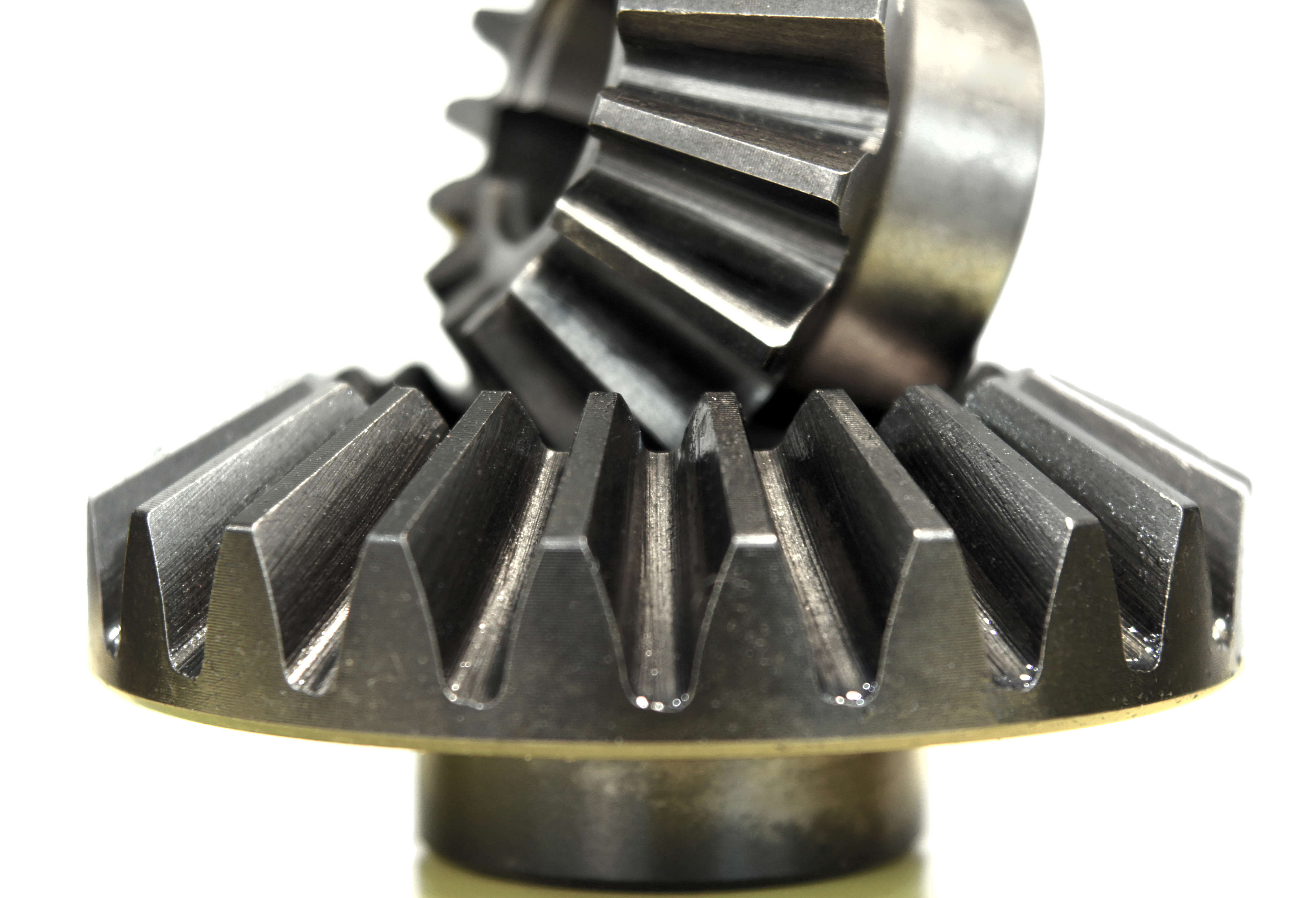
For intersecting axes, the most common style of gear is the bevel gear. The term bevel gear is used to describe both a specific type of gear and any of a variety of derivatives of this style. When bevel gears are mated with a speed ratio of one-to-one, they are called miter gears. For any other ratio they are called bevel gears.
and the spiral tooth form.
Although bevel gear sets can be produced with fractional speed ratios greater than one-to-one, the pinion and gear are produced such that they will only mate with one another at a certain intersecting angle. Most bevel gears are produced for intersecting shafts set at 90 degrees, but there are bevel gears produced with shaft angles as small as 45 degrees and as large as 135 degrees. The most common style of bevel gear is the straight tooth bevel gear. This gear has teeth that are a tapered conical form and lay in the same direction as the pitch cone base line. The standard bevel gear tooth form is identical for both the bevel pinion and the bevel gear. This becomes a limiting factor for large speed ratios as the pinion is inherently weaker than the gear. The Gleason bevel gear tooth form considers the speed ratio of the bevel gear set to determine the tooth shape of both the pinion gear and the bevel gear and enlarges the pinion tooth in higher ratio sets. Even with this additional compensation for tooth loading, bevel gear sets are typically limited to speed ratios of six to one.
The second most common bevel gear style is the spiral bevel gear. The tooth of the spiral bevel gear is similar to that of a helical gear in that the tooth is produced at an angle to the bore axis. Spiral bevel gears are also produced such that if the pinion has a left-hand spiral, the mating bevel gear must have a right-hand spiral of equal angle. The most common spiral angle for bevel gears is 35 degrees. Similar to the thrust loads produced by the helix angle, there are thrust loads in spiral bevel gears that result from the spiral angle.
A third tooth style for bevel gear sets is the Zerol bevel gear. This style of bevel gear is a hybrid that lies between the straight tooth form and the spiral tooth form. Unlike the spiral bevel gear in which the tooth is generated at an angle to the axis, the Zerol gear tooth is generated at an angle of zero degrees but unlike the straight tooth bevel gear where the tooth is a taper conical form, the Zerol gear tooth is curved. This results in a spiral bevel style gear that mimics the loading pattern of a straight tooth bevel gear. A specialty case of intersecting axes gearing is the face gear. This is a gear set in which a spur gear is used as the pinion and a disc with tapered teeth is used as bevel gear. This style offers no operational advantages over a standard bevel gear set.
For nonparallel and nonintersecting axes applications, the most common style of gear is the worm gear pair. This pair of gears includes the worm wheel, which is basically a helical gear, and a worm, which is screw thread that matches the pitch, pressure angle, and helix angle of the worm wheel. The speed ratio of a worm gear pair is determined by the number of teeth on the worm wheel and the number of thread starts on the worm. For worms with a single thread, very high speed ratios can be developed. When adding additional thread starts, the helix angle needs to increase if the center distance is to remain the same. Another type of nonparallel-nonintersecting gear is the screw gear (also known as a crossed helical gear). This is a helical gear set in which the gears operate any angle greater than zero degrees. The most common angle is 45 degrees. As with helical gears, an infinite variety of fractional speed ratios are possible, but due to the mesh being point contact, these gears have a limited load capacity.
A specialty case of nonparallel-nonintersecting axes gearing is the hypoid bevel pair. In this set, the larger gear looks similar to a spiral bevel gear; however, the pinion sits offset to the intersecting axis, and its tooth form resembles a tapered thread. Similar to worm gear pairs, the speed ratio of a hypoid set is determined by the number of thread starts on the pinion relative to the number of teeth on the mating gear. As such, a hypoid configuration can result in very high speed ratios in a very compact space.
As detailed in these examples, there are many distinct styles of gearing. Each has a purpose, and each application will dictate what style should be selected.
About the author: Brian Dengel is general manager of KHK-USA, which is based in Mineola, New York. Go online to www.khkgears.us.


