


This column covers joint design for laser welding. Last month joint access and restraint were discussed, and next month material considerations are to be presented. After completion of this series on design, columns relating to the weld process will follow.
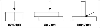
The basic joint designs for laser welding are similar to those for other welding processes, except that welding with a laser is commonly performed autogenously; or, rather, without filler material. Figure 1 illustrates the styles classified as butt, lap, and fillet joints. The most remarkable difference between laser welding and the arc/conduction mode processes is that laser energy can deeply penetrate a joint, producing good joint coverage without filler material being added. The joint designs of Figure 1 do not show any preparation for filler material, such as a V or J groove. Because joint machining is minimized and filler is not used, some cost savings are realized immediately.
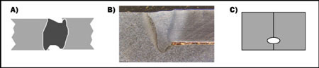
The butt joint is the most common design seen in industry. The strength provided by this design is in large part determined by the contact length, or penetration. As discussed last month, a joint of this type should be designed for full penetration to minimize restraint. Intimate contact between the surfaces to be welded is ideal. Any gap that is present should be less than 10 percent of the total joint contact length or less than 50 percent of the focused beam diameter. In consideration of the joint length, excessive gap can lead to a “lack of fill,” demonstrated by an undercut crown (negative reinforcement) as shown in Figure 2a. If the gap is too large compared to the focused beam diameter, the laser may not interact with the material properly and reflect or tunnel down the joint line. When the butt joint design is used, proper alignment of the components can be facilitated by providing a step as shown in Figure 2b. The step adds to the robustness of the process by maintaining alignment and prevention of over-penetration, which can result in negative reinforcement at the crown. The design of the butt joint with this step feature should consider providing adequate material to allow over-penetration of the joint without break-through, and consideration of that restraint does not present itself at surfaces away from the joint itself. If a butt joint cannot be designed for full penetration, with or without a step for alignment, the problem of restraint can be minimized by providing a groove in one or both of the components, as shown in Figure 2c. In performing a partial penetration weld the joint line can act as a crack initiator. By placing a groove at the penetration limit this inherent “crack” will be blunted, minimizing the potential of a crack forming at the root of the weld.
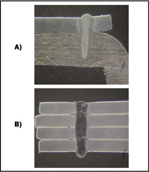
The lap weld is the second most common joint design used, and is very forgiving from the standpoint of alignment relative to the desired location of the weld. As long as the components are in contact, a system with low tracking accuracy can easily join the components. It is not unusual to see this design used to join multiple stampings made from sheet stock. Like the butt joint, the gap between the components should be kept to less than 10 percent of the thinnest layer. Figure 3a shows a common two-component lap weld with partial penetration of the lower member. In figure Figure 3b a multilayer lap weld is used to produce a muffler from sheet weld stampings using full penetration. The strength of this joint is dependent upon the width of the laser weld. Some variation in width can be accomplished by process adjustments, but if a stronger union is required, then multiple welds may be required.
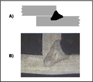
The fillet joint is the least utilized design when employing laser welding. It is similar to the butt joint except that there is significant mismatch in component width at the joint line, requiring an angular approach to access the joint. Two variations on the fillet joint are shown in Figure 4. In Figure 4a two plates are face-to-face, and in Figure 4b two plates are edge-to-face, forming a T. The same rules for gap tolerance that applied for the butt joint design apply to the fillet joint as well. When no filler material is used in creating a fillet weld it is common to have a negative reinforced crown. The combination of restraint in design and negative reinforcement can lead to tearing (cracking) at the surface of the weld if not performed properly. Components should be designed with a line-to-line or interference fit if components exhibit restraint on the fusion zone.
This is meant for those intending to employ an autogenous laser welding process. Over the last five years it has become common practice to present filler material to improve the robustness of laser welding technology. Although processes are available that can provide filler material, it is best practice to design for autogenous laser welding in an effort to realize the benefits of this highly efficient technology.


