


By Prof. Dr.-Ing. C. Brecher, Dr.-Ing. C. Löpenhaus, Julian Theling,
Marius Schroers, and Dipl.-Ing. Daniel Piel
Tooth flank modifications are used to optimize the excitation behavior and durability of gears. In the first step, design is often done via guidelines, and afterwards, a variety of tooth flank modifications is checked via local calculation approaches to determine the best micro geometry in order to enhance operational behavior. Modifications are subject to statistical deviations due to the manufacturing process. Their sizes are in the range of micrometers and therefore in the same dimension as the tooth flank modification itself. However, deviations are often not taken into account during the design of modifications today, although they can lead to an uncertain influence on the operational behavior.
The authors developed a method to evaluate the quality and stability of flank modifications (such as: tip reliefs, profile angle modifications, profile crownings, lead angle modifications, helix crownings, end reliefs, and root reliefs) regarding manufacturing tolerances during the design process. An FE-based tooth contact analysis is used to simulate characteristics of the excitation behavior and durability of a gear pair. In addition to the standard design process, the tolerance field of the tooth flank modification is taken into account. In order to choose an optimized micro geometry, a weighting function is used to compare the results by quality (level of target value such as transmission error or stress) and stability (variability of target value) under consideration of all relevant combinations of relevant modification parameters on pinion and gear in their respective tolerance fields.
By means of the developed method, the planetary gear and cylindrical gear stages of a wind turbine are optimized. Regarding the target values (Hertzian pressure, transmission error, and root stresses) the characteristics for quality and stability are calculated, and the best constellation of tooth flank modifications is chosen. Results suggest that the quality of tooth flank modifications can differ between chosen tolerance fields while some variants are more susceptible than others. The presented design process provides a method to examine those influences and enables the engineer to choose the most robust micro geometry in terms of quality and stability already in the design process.
1: Introduction
Modern transmissions have to fulfill more and more customer and legal requirements. The design objectives that have to be achieved are contradicting, and the best solution is not immediately evident (Figure 1). On the one hand, the costs of the manufacturing and design process have to be reduced, and on the other hand, the durability and excitation behavior have to be improved. At the same time, the developed design has to be manufacturable and provide a high efficiency.
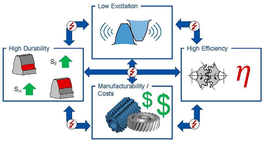
The main source of excitation in transmissions is the tooth contact. The durability and the excitation behavior can be improved through tooth flank modifications. Nevertheless, designed tooth flank modifications, which lead to a good noise behavior, do not automatically lead to good durability or efficiency.
Like any manufacturing process, the grinding of tooth flank modifications is subject to systematical and statistical deviations [2]. These deviations are caused by errors in the machine kinematics, deviations of the grinding wheel or the workpiece. The tolerance field describes the allowed deviations from the nominal values. Thus, a smaller tolerance field leads to smaller deviations. Nevertheless, with a smaller tolerance field, the manufacturing costs increase through longer cycle times and a higher amount of scrap parts. Because of the interdependence between the design goals, the optimization of one by one does not lead to the achieved design objective. Therefore, it is important to describe the interactions and influences between the design objectives and regard them during the design process to generate the best solution.
Today, if the excitation behavior or the durability in one design is spread over a wide bandwidth, the tolerance field is often decreased. As mentioned before, a smaller tolerance field leads to higher manufacturing costs. In addition, the design can behave dramatically within the tolerance field, which means that small deviations from the nominal tooth flank geometry can cause high excitations or flank pressures, even when the nominal design shows good results.
The objective of this exercise is to provide a method that regards the stability of the nominal design inside given manufacturing tolerances. With the help of this method, it will be possible to choose the nominal design most robust in running behavior regarding geometric undesired deviations. In addition, it will be possible to take different load cases and weightings of the functional target parameters such as stresses or transmission error into account dependent on the load case. The design approach is presented by means of a quasi-static tooth contact analysis and the results confirmed via a dynamic 1D simulation afterwards.
2: Background
The following chapter deals with the initial motivation of the described method. First, the standard design process of transmissions is presented, starting with the customer`s requirements over the conception and dimensioning up to the optimization of the tooth contact (Figure 2). Afterwards the FVA project “FVA Gondel” and the gearset which the method was applied will be shown.
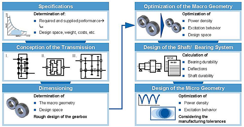
The design process of gearboxes follows the rules of the standard design process in mechanical engineering according to PAHL and BEITZ. The steps that have to be taken include the design specification, the definition of the concept, the development of a preliminary layout, and the optimization of the preliminary to a definitive layout [3].
The first step of the design process is to determine the requirements of the customer. The main aspect in the design of gearboxes for wind turbines is to transmit the provided power from the input to the output shaft and change the input torque and rotational speed to the required values. Therefore, the overall gear ratio is defined and a requirement list is written.
In the second step, a concept is developed. Main tasks are to establish the function structure to provide the given overall gear ratio and identify essential problems like weight or design space requirements, which cannot be fulfilled. After this step the number and type of the gear stages are defined.
The total gear ratio is split up on the gear stages in the third step. Regarding durability standards and experiences, the macro geometrical values are calculated and optimized afterwards. After this step, the numbers of teeth, profile angle and other macro geometrical values like the center distance are fixed. With the given geometry and provided torque and rotational speed the bearings and shafts can be designed. The definition of the micro geometry is the fourth and last step in the gear-design process. It is used to optimize the durability and the excitation behavior regarding load dependent deformations and displacements. By means of the optimization of durability and excitation behavior, the power density and the running behavior can be improved. Often it is done via FEA or an FE-based tooth contact analysis combined with a multi-body simulation. Different tooth flank geometry variations are developed by means of internal and external guidelines and simulated afterwards to define the best design.
2.1: Project ‘FVA Gondel’
The presented method is applied to the design of the gearbox of a 2.7 MW wind turbine. The optimization of the tooth geometry was part of the project “FVA Nacelle” (FVA 730), in which a nacelle is tested on a 4 MW test rig to determine the influences between the different components of a wind turbine [4]. The project is funded by the BMWI (Federal Ministry of Economic Affairs and Energy) and is coordinated by the CWD (Center for Wind Power Drives), where the test rig is assembled. Other funded partners in the project are the FVA (Research Association of Drive Engineering) and Siemens AG-Winergy. Realistic wind scenarios as well as synthetic load cases are tested and characteristics of the excitation and load situation are measured at the gearbox and other components by means of over 250 sensors. Regarding the measured data, the behavior of the transmission is analyzed and interdependencies are determined. Furthermore, the testing results are used to validate the design and modeling software of the FVA Workbench Software Stirak for large module gearsets and high torque transmissions. The rotor of the wind turbine is simulated by a 4 MW direct drive. In order to provide realistic test scenarios, wind forces are applied with a non-torque load unit in all degrees of freedom. The tested nacelle uses a gearbox generator setup to convert the kinetic rotor energy in electrical energy. The gearbox consists of a planetary gear stage on the input side and two cylindrical gear stages (Figure 3). The gearbox is a modified legacy gearbox of Siemens AG-Winergy.
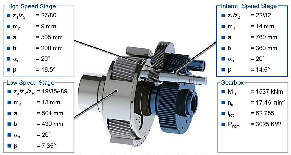
With a nominal input revelation speed of 17.46 rpm and a nominal torque at the input shaft of 1537 kNm, the gearbox has a nominal power of 3,025 kW. The gearbox is part of a NECMICON 2.7 MW wind turbine and has a total gear ratio of i = 62.755. The rotor of the wind turbine is connected to the planet carrier, in which three planets with zP = 35 teeth are mounted. The ring wheel is fixed to the housing and has zR = -89 teeth. The planetary gear stage has a normal module mn = 18 mm and all stages have a profile angle αn = 20°. The sun shaft with zs = 19 teeth is output of the low speed stage, which is connected to the intermediate speed stage over a curved-tooth coupling. Normal module of the second stage is mn = 14 mm. The wheel has z1 = 82 teeth and the pinion has z2 = 22. The nominal output speed of the second stage is approximately 305 rpm. The wheel of the high-speed stage is mounted on the same shaft as the pinion of the intermediate speed stage and has z3 = 80 teeth. The pinion with z4 = 27 teeth is mounted on the output shaft of the gearbox, which is connected to the generator. All gear stages are designed as helical gears, due to better overlap ratios.
3: Design of Tooth Flank Modifications
The procedure of how to correctly choose the optimal micro geometry is illustrated in Figure 4. The surrounding elements have an influence on the tooth contact and have to be regarded during the design process. Therefore, the load dependent deformations and displacements of the shaft and bearing system are calculated in the first three steps and then transformed on the tooth contact to regard it during the variant calculation. The load dependent displacement can be regarded as a polynomial function in the variant calculation to reduce the calculation time and have the information about the load dependency in one simulation model.
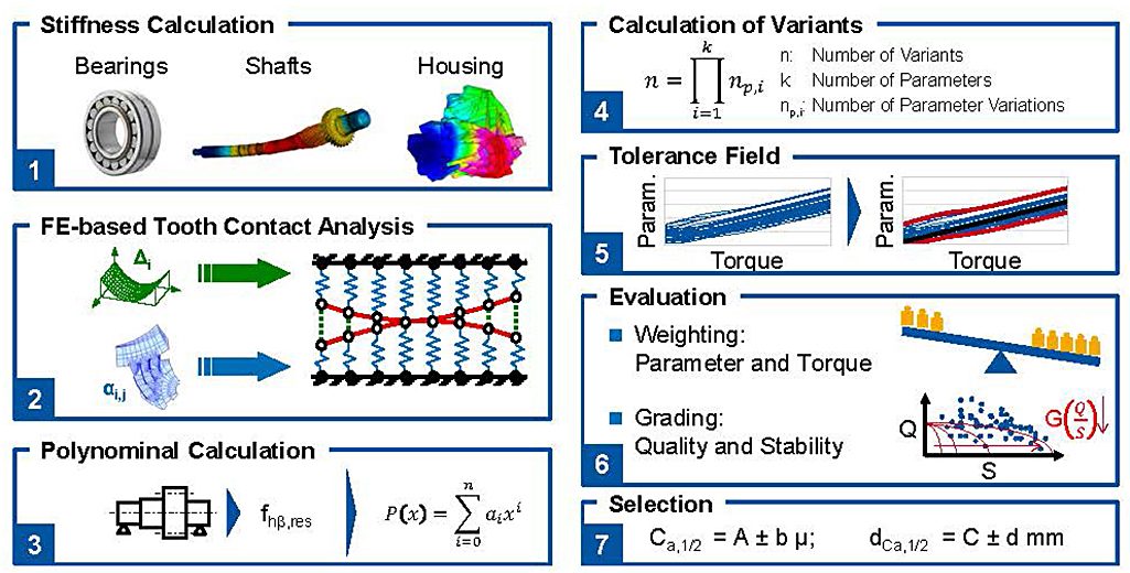
First, the load-dependent stiffness of the surrounding elements is calculated [1]. The bearing stiffness as well as the housing, shafts and the planet carrier can be regarded during this design step. Particular load cases with their respective surrounding stiffness are calculated using an FE-based tooth contact analysis [2]. With the information of the deviation behavior by means of the calculated stiffness and the load cases a polynomial is defined. Therefore, at different loads, the lead angle deviation is obtained from the first two above-mentioned steps. A load-dependent polynomial [3] is then derived from the deviations. In the case of tooth trace deviations, the polynomial usually can be reduced to a linear function. This polynomial is necessary in order to consider the load-dependent deflection of the shafts and the gears during the variant calculation, which is the main part of the optimization process [4]. The design-relevant parameters are determined by the variant calculation using parameters of the tooth flank modifications in a predefined limit and its appropriate step size. The operational torque is varied as it has an important impact on the optimization. By this, all design-relevant parameters are obtained at the end.
The variant calculation delivers a large number of variants, which needs to be analyzed. The aim is to determine the best tooth flank geometry. The parameters are assessed by an automated process, which takes into account the different parameters’ importance and torque as well as the grading of specific results. Furthermore, monitoring of the system’s stability is performed. This means, that for each nominal design, the limits of a predefined tolerance field are considered, for instance as per DIN 3962 [5, 6]. By this, the sensitivity of a given design to possible manufacturing deviations can be determined. The results are processed and the design with the best total grade is chosen.
3.1: Calculation of the Load Dependent Displacements
In order to find the best tooth flank micro geometry, the load dependent characteristic of the surrounding elements have to be regarded. Two different approaches are chosen for the cylindrical and the planetary gear stage. The load dependent bearing stiffness of the cylindrical gear stages are calculated by means of the software Bearinx provided by the company Schaeffler. The same approach is chosen for the four bearings mounted in each planet wheel. In addition, the four planet bearings are coupled in a simple spring model and an equivalent stiffness is calculated and used in the FE-based tooth contact analysis afterwards. Furthermore, the load dependent displacement behavior of the planet carrier is simulated by means of the FE modeling software Abaqus for different load cases and a stiffness value is derived.
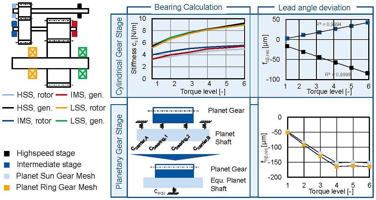
In Figure 5 the resulting lead angle deviations and bearing stiffness for the cylindrical and planetary gear stages are shown. In order to regard the load dependency of the bearing stiffness, the calculated torque bandwidth is clustered into six nominal torque steps. Starting with 25 percent nominal torque and culminating in 150 percent nominal torque with a step size of 25 percent nominal torque. The FE-Stirnradkette, an FE-based tooth contact analysis is used to determine the resulting lead angle deviation. Therefore, two FE-Models are generated. One consisting of the two cylindrical gear stages modeled as a gear chain to regard the interdependencies of the two gears on the intermediate shaft, the other consisting of the gear chain sun, planet, and ring gear. Because of the symmetrical structure of the planetary gear stage, only one planet is modeled as a gear. The other two planet gears are represented in the Stirak model by tangential and radial forces, which are applied on the sun and ring gear. Hence, the impact of the two remaining planets on the torsion of the sun gear and sun shaft is considered.
The upper row of the figure depicts the calculation results of the cylindrical gear stages. The bearing stiffness shows a load dependent behavior. The IMS and HSS bearings on the rotor side as well as the IMS bearing on the generator side are roller bearings. The remaining bearings are angular ball bearings. Thereby the similar stiffness graphs for these positions can be explained. By means of the bearing stiffness and the shaft modeling within the FE-based tooth contact analysis, the resulting lead angle deviation is calculated for the six load cases. The resulting lead angle deviation can be approximated in good accordance by a linear function and will be regarded as such in the following calculations.
In the lower row, the calculation approach and results for the planetary gear stage is presented. In order to regard the displacement behavior within the tooth contact analysis, an equivalent stiffness has to be calculated. This is reasoned in the modeling approach in which bearings can only be mounted in shafts and not in the gear body itself. With the bearing and carrier stiffness, an equivalent stiffness is calculated. In contrast to the helical gear stage, the resulting lead angle deviation shows a constant value for torque levels higher than 100 percent nominal torque. This behavior can be explained by a contact of the roller with the shoulders of the inner ring, which results in a much higher tilting rigidity.
The determined lead angle deviations are regarded in the further analysis. Dependent on the input torque different lead angle deviations are applied on the tooth contact. Hence, the tilting of the tooth mesh plane is taken into account, and the characteristic values of excitation and durability for the load cases can be calculated.
3.2: Design Space and Tolerance Field
A big advantage of the FE-based tooth contact analysis is the fast calculation of different variants, which have the same macro geometry. Therefore, a large amount of micro geometrical variants can be investigated during the design process. The investigated range of tooth flank corrections is defined by literature and experiences of the designer.
At the cylindrical gear stages, the investigated tooth flank modifications in profile direction are profile angle corrections, profile crowning, and the value of the tip relief. In flank direction, the lead angle correction, flank crowning, and the value of end reliefs are investigated. The length of the end and tip reliefs are calculated by means of the approach of Niemann/Winter [7]. With the definition of an upper and lower limit for each parameter and the step size, the number of variants at the IMS amounts to 18 670 176 and at the HSS to 33 191 424 variants. The calculation for both gear stages lasts 78 hours.
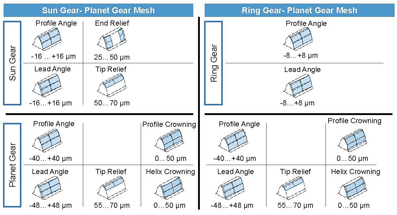
Figure 6 depicts the variation parameters of the planetary gear stage for the sun, planet, and ring gear. Within these parameters, the tolerance field is included and the corresponding values are picked afterwards. The optimization of the planet gear is restricted by the condition, that the left and right flank are modified in the same way. The number of calculated variants amounts to 1 111 968 at the ring gear planet mesh and 37 065 600 variants at the sun gear planet mesh. The calculation of both meshes lasts 56.7 hours.
The upper and lower limit of the tolerance field is defined by the step size of the variant calculation. Therefore, the incremental step size for each parameter is chosen regarding standard tolerance field widths. This definition reduces the calculation time because other nominal designs can be used as limits of the resulting tolerance fields. Only nominal designs at the side of the parameter field cause additional calculations.
3.3: Weighting of the Parameters
In contrast to industrial gearboxes, which often operate at a constant operating point and therefore, are often designed for one load case, the gearbox of a wind turbine has to be designed for variable loads. In order to take these influences into account a weight function is developed. For this gearbox the assumption is made that the nominal torque level is the most common load case. The other load cases are weighted by means of normal distribution (Figure 7).
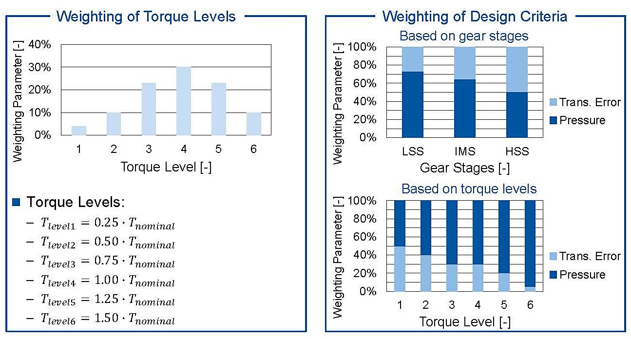
Within the design process, two design criteria are identified. The design criteria are a high durability and a low excitation caused by the tooth mesh. As characteristic values, the transmission error is chosen to represent the excitation behavior and the maximum tooth flank pressure is chosen to consider the durability. The main influence of tooth root stresses is the macro geometry of the gear stage. Because the macro geometry of all stages is already fixed, the tooth root stresses are not part of the design criteria of this project. Nevertheless, the presented method is able to regard other design criteria such as tooth root stresses or efficiency as well. Within the load cases, different weightings are chosen. In the low load sector, the durability of the gearset is not put at risk and the excitation behavior is rated more important. With rising torque, the durability gets more important and the excitation behavior is weighted with a lower factor. Besides the differentiation between load cases, the gear stages are weighted different. The focus of cylindrical gear stages with higher rotational speeds is on the transmission error, because with higher speeds, the excitation and noise of the gear stage is more conspicuous for human hearing [8].
After the definition of the weighting factors, the results have to be quantified. Therefore, a grading system is used with marks from one to six. The mark one represents the best, the mark six the worst value. To select the represented values for each mark, different approaches have to be used for the transmission error and the tooth flank pressure. In order to cluster the tooth flank pressure, the material characterization for pressure loads is used. Calculated flank pressures with a value above 1,500 MPa are graded six, a pressure of or below 500 MPa is graded one. In order to cluster the transmission error, the material data cannot be used, because the excitation behavior is strongly dependent on the transmission concept and the macro geometry of the gears. Therefore, the grading of the variants is done afterwards.
The highest occurring transmission error is graded six, the lowest occurring one with the mark one. The other marks are spread linear between these two values.
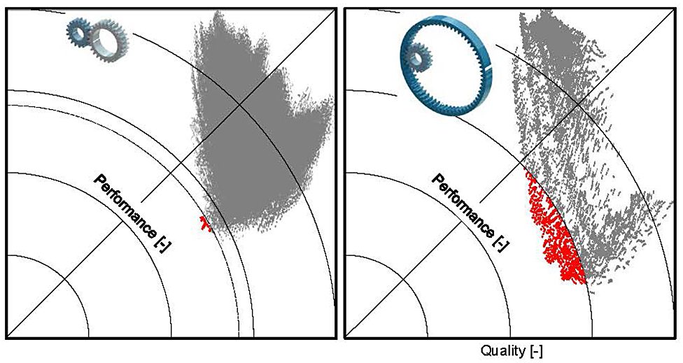
With the combination of marks and weighting factors, an overall score for the quality of each variant is determined. Therefore, all values are multiplied, and the worst/highest score is normed to one. In order to regard the different results within one tolerance field, a value for the stability of each design is calculated. For the stability, the standard deviation to the nominal design of the overall score of all geometries within the tolerance field of one variant is calculated. The widest spread in one tolerance field is normed to one afterwards. The calculation results for all variants of the planetary gear stage is shown in Figure 8.
The left graph presents the results of the sun planet gear mesh calculated by Stirak and weighted afterwards. It can be seen that the results within the parameter field differ. An optimal variant that is stable in its tolerance field and has a good quality at the same time, would be found in the lower left corner of the diagram. The circles in the diagram represent values with the same degree of performance. In this case, quality is as important as stability. The right diagram presents the results of the planet ring gear mesh. Both diagrams show that micro geometry variants with a good stability performance show not automatically a good quality and vice versa.
For further investigations, the results are reduced. Therefore, all variants within a performance value lower than 0.7 at the sun gear mesh and lower than 0.75 at the ring gear mesh are determined. The number of results are reduced by the restriction that the modifications on both flanks at the planet gear have to be the same. After this reduction, only five possible micro geometry designs are left at the planetary gear stage and further investigated. The same approach is applied to the two cylindrical gear stages.
3.4: Final Design
Figure 9 depicts the load-dependent results of the cylindrical gear stages with consideration of the tolerance field deviations of the tooth flank modifications and the deflections caused by the shaft-bearing-system. The results from the intermediate speed gear stage (IMS) are represented in the left diagram and the results from the high-speed gear stage (HSS) are illustrated in the right. The upper two diagrams show the transmission error, whereas the bottom two show the flank pressure. The illustration compares the nominal design of the tooth flank modifications to the best and worst possible combinations, which could be derived from the analysis of the tolerance field. The best and worst-case lines show a range around the nominal torque, which is analyzed with the dynamic simulation model in the next chapter.
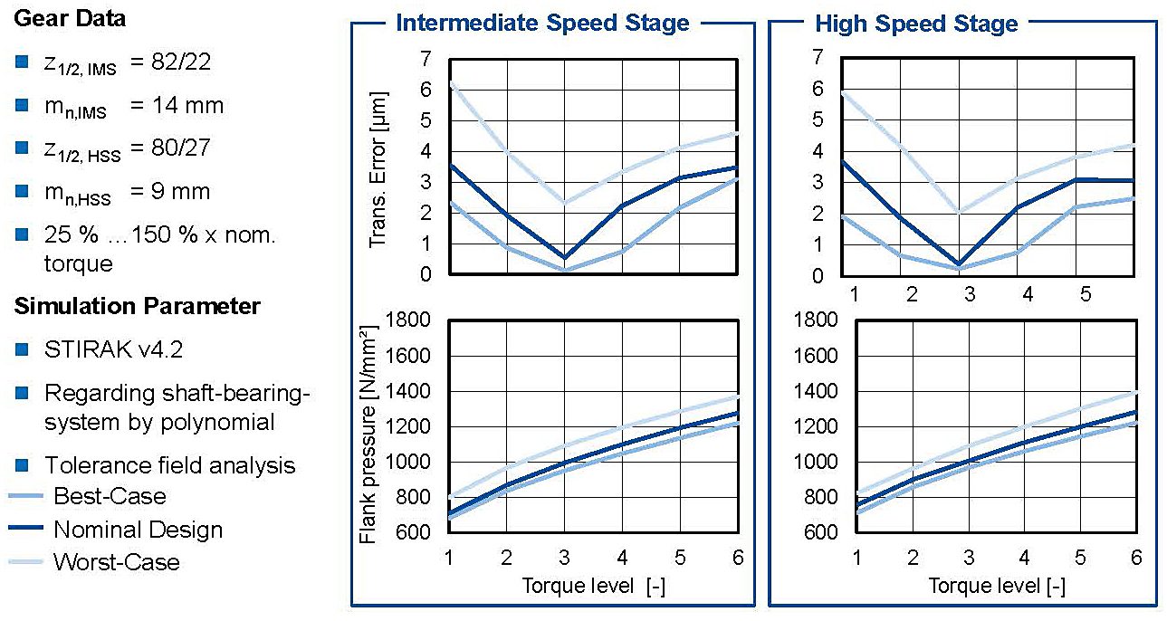
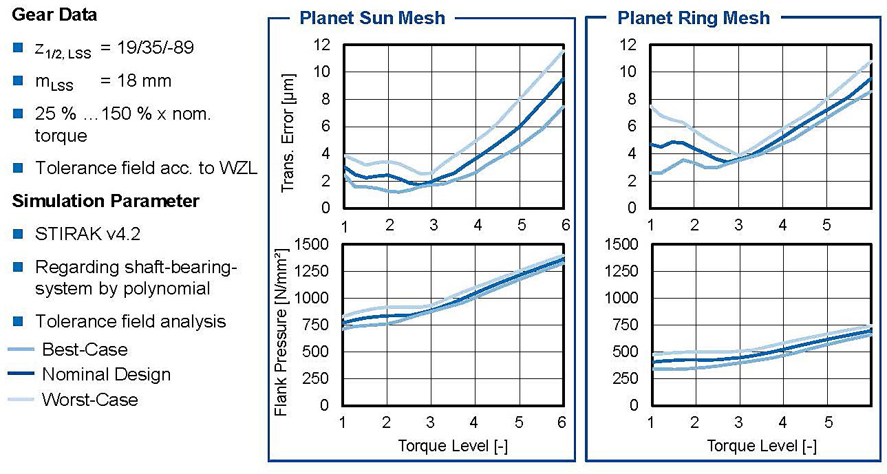
For the transmission errors in the upper row, it can be seen that local minima occur at 75 percent of the nominal at torque level 3. In this torque range, the excitation behavior has been weighted more heavily in the selection of the flank modifications compared to the load carrying capacity aspects. The influence of the flank modifications on the flank pressure can be seen in both gear stages. Even at 150 percent nominal torque, the flank pressures do not reach critical values for short-term operation. The scattering of the flank pressure by the manufacturing tolerances is very low and does not lead to a critical deterioration if an unfavorable combination from the manufacturing deviations results. Figure 10 shows the results of the chosen micro geometry of the planetary gear stage meshes. On the left side of the diagram, the results of the planet sun mesh are presented, and on the right side, the results of the planet ring gear mesh are shown. In the upper two diagrams, the transmission error is depicted; in the bottom two, the flank pressure is plotted.
The calculation results of the planetary gear stage show a similar behavior. The graphs of the planet sun and planet ring gear mesh change their behavior at 75 percent nominal torque. In the planet sun gear mesh, the transmission error in lower torque levels is stable between 1.5 and 4 µm. The difference within the tolerance field stays at similar values in higher torque levels, even though the transmission error itself rises. In lower torque levels, the difference between the best and worst design case at the ring gear mesh shows high values. The difference at 25 percent nominal torque are 6 µm, which is 150 percent of the nominal transmission error. With higher torques, the transmission error within the tolerance field approaches to the nominal value, until a local minimum is reached at 75 percent nominal torque. In higher load cases, the transmission error shows a linear behavior for the ring gear mesh and the variants in the tolerance field act very stable. Local minima at torque level three, occur because of the tooth flank corrections. The stability of the calculated pressure values is very good within the tolerance field for both meshes. The lower left graph depicts the calculated flank pressure values for the sun planet gear mesh. In low torque levels, the flank pressure is calculated to values between 750 and 900 N/mm2. Similar to the transmission error the behavior changes at 75 percent nominal torque. With higher torque levels, the flank pressure rises linear to 1400 N/mm2 at 150 percent nominal torque. Results of the ring gear mesh are presented in the lower right graph. In low torque levels, the calculated flank pressure stays between 300 and 500 N/mm2. At torque level three the graph starts rising linear with a lower gradient than the other gear stages. At 150 percent nominal torque a flank pressure of 750 N/mm2 is calculated at the ring gear mesh, which is 50 percent of the critical 1,500 N/mm2 for short term-operation. The lower values at the ring gear mesh result out of the concave-convex contact, which provides better contact conditions and therefore a lower tooth flank pressure.
4: Calculational Analysis of the Dynamic Excitation Behavior
In this chapter, the dynamic excitation behavior is analyzed by means of the results of a dynamic simulation model. First, the setup of the simulation model is described. Hence, the results are analyzed in order to determine the influence of the manufacturing deviations on the excitation behavior.
4.1: Setup of the Dynamic Simulation Model
Due to varying requirements and working conditions during the operational use of gearboxes, the operating conditions (for example torque and rotational speed) are not constant. For special operational points, the overload can be critical for the load carrying capacity and the excitation behavior. Mostly, the critical operational points occur when the excitation frequencies coincide with eigenfrequencies of the test setup. In this case, a quasi-static investigation is not effective, and a dynamic analysis is necessary. Figure 11 illustrates the two main components and their interaction. The force coupling element represents the gear mesh, and the drive train model includes the properties of the gearbox and the entire drive train.
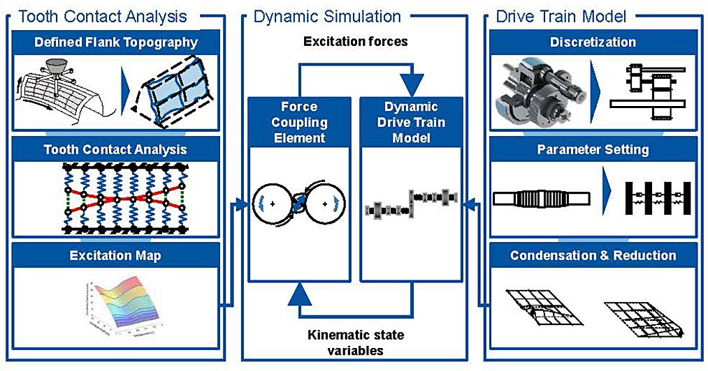
The force coupling element requires a subroutine of the tooth contact analysis FE-Stirnradkette that is developed at WZL [9]. FE-Stirnradkette enables the calculation of excitation maps based on input data; see Figure 11 on the left. As data, the gearbox structure, the macro and micro geometry of the gears, and tool data is needed. Depending on the load-dependent transmission error and the current angular position of the gear, actual excitation forces and torques can be determined.
The approach to build up the drive train model is presented in Figure 11 on the right. The objective of this step is to provide the system matrices for the simulation (inertia, stiffness, and damping). In this paper, only the torsional degree of freedom is regarded, and the setup is limited to the cylindrical gear stages. Due to the domination of rotational excitation of the gear mesh, this assumption is suitable. The first step in the approach to design the drive train model, in Figure 11 on the right, is the discretization. In this step, the drive train is divided into discrete inertias. Each inertia is connected to its neighboring inertias by massless spring-damper units. Subsequently, the numerical values of the parameters are determined. Simple components can be parameterized using analytical equations. Furthermore, the inertia of the non-cylindrical components can be extracted from CAD models. However, some parameters are difficult to calculate, such as the contact stiffness of frictional connections, form closures, and damping. An iterative procedure based on experience values has been established to compare measurement and simulation results when setting parameters for these components.
The first two steps of the approach generate models with a high number of degrees of freedom. Hence, the numerical solution of those systems would be uneconomically long, and the numerical accuracy would be decreased. To avoid both disadvantages, a modal reduction of degrees of freedom by Craig and Bampton is performed [10]. The frequencies within the acoustically relevant frequency range are not reduced and only high eigenfrequencies are neglected. Therefore, this reduction method is suitable.
The interaction between the force coupling element and the drive train model is shown in the middle of Figure 11. For each time step, the drive train model transfers the kinematic state variables (angle of rotation and rotational speed) to the force coupling element. Depending on the input data, the force coupling element determines the excitation forces with excitation maps and returns them to the drive train model. The excitation forces are composed of a variable tooth stiffness term and a damping term. The tooth stiffness term is determined by the aforementioned excitation maps from Stirak. In contrast, the damping term uses a velocity proportional approach. With the excitation forces and the generated system matrices, the differential equations can be solved. This procedure will be repeated for each time step.
4.2: Analysis of the Results of the Dynamic Simulation Model
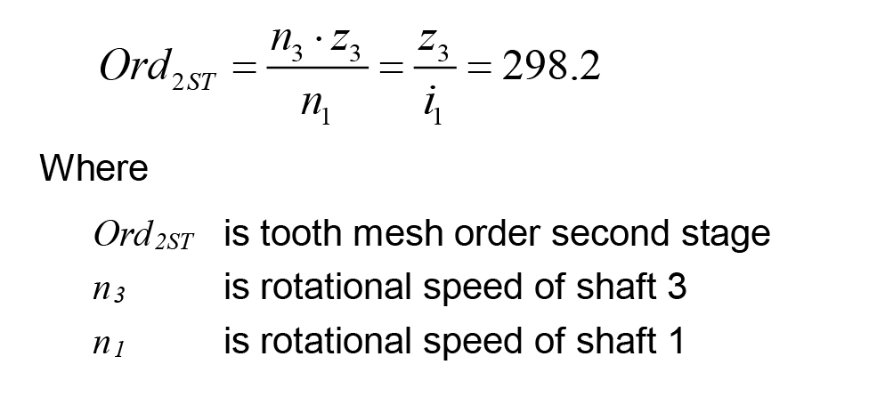
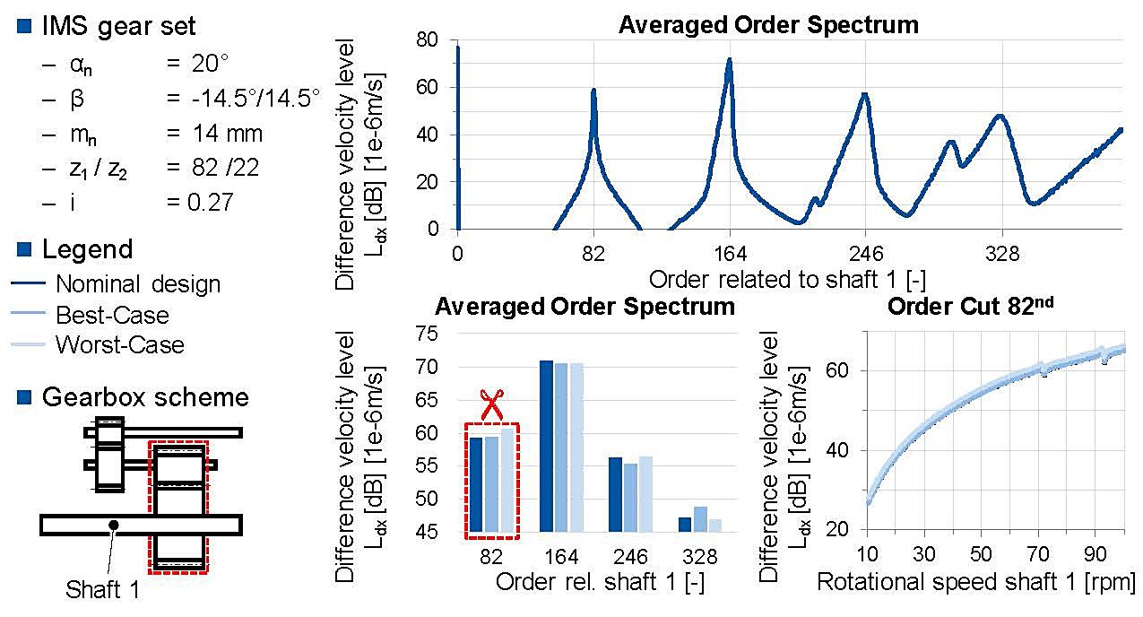
In this section, the dynamic excitation behavior of the cylindrical gear stages of the wind-turbine gearbox will be analyzed and evaluated on the basis of calculation results from the previously introduced simulation model. For the rotational speed run-up, the results of the difference velocity of the IMS are depicted in Figure 12. The difference velocity is the time derivative of the transmission error and is suitable to analyze the dynamic excitation behavior [7]. In the averaged order spectrum, the gear mesh orders of the IMS are the 82nd and their harmonics referred to the rotational speed n1 of the IMS input shaft (shaft 1). The gear mesh orders of the HSS can be calculated with Equation 1. The order spectrum is dominated by the orders of the IMS. Consequentially, the mutual influence between the two gear stages is low.
In order to analyze the robustness of the flank geometry design and the influence of the manufacturing tolerances, three micro geometry variants for every gearset are considered for the rotational speed run-up at nominal torque. Besides to the nominal design, the first four gear mesh orders of the IMS a combination of flank modifications of a higher (worst case) and a lower (best case) transmission error are taken into account (compare Figure 9). The excitation behavior is analyzed in Figure 12 on the bottom left. For the first and third gear mesh order, the excitation level of the worst flank topography (60.6 dB) is higher than the two other variants (both 59.3 dB). In contrast, the excitation level of the second order is similar for all variants. The excitation course of the first order is analyzed deeper by means of an order cut in the bottom right of Figure 12. For the whole run-up, the difference velocity level increases and the worst-case variant has the highest excitation level again. The results of the dynamic simulation model confirm the robust design which has been developed with the quasi-static approach in chapter 3. The results of the nominal design and the best- and worst-case are in a small scatter band.
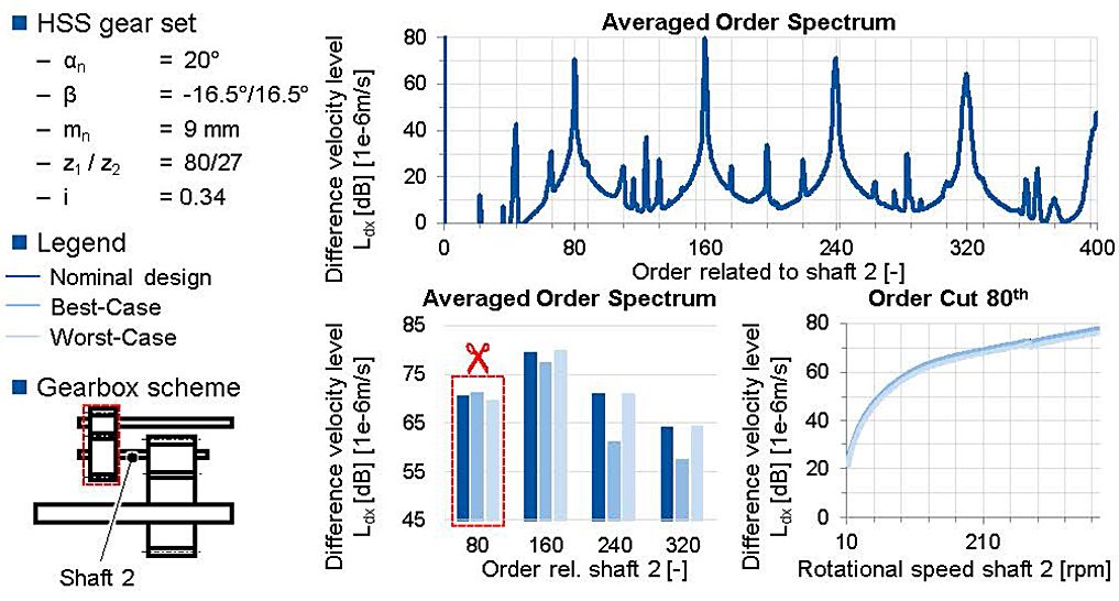
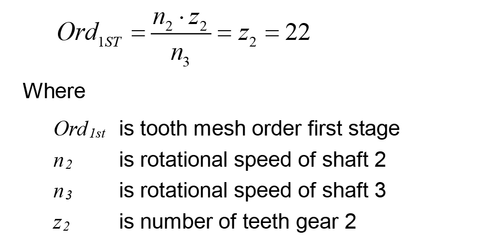
The results of the HSS are shown in Figure 13 for the same rotational speed run-up of the IMS. In this case, the averaged order spectrum in the top line is referred to the rotational speed of the input shaft of the HSS (shaft 2 = IMS output shaft). The order of the HSS gear mesh corresponds to the 80th order and their harmonics. According to Equation 2, the order of the IMS can be calculated. Besides the gear mesh orders of the IMS and the HSS, there are some more orders, which are caused by the interactions between the gear stages. Nevertheless, the averaged order spectrum is dominated by the gear mesh orders of the HSS.
Similar to the analysis of the IMS, a comparison of three different flank modification has been performed for this gear stage (compare Figure 9). For the first gear mesh order, the best-case modifications have the highest excitation level. In contrast, the best-case modifications have the lowest excitation level for the higher gear mesh orders. The excitation level of the nominal and the worst-case design is similar for the first four gear mesh orders. Following, the nominal design based on the quasi-static approach in chapter 3 cannot lead to a higher excitation level caused by a bad combination of manufacturing deviations (worst-case). In fact, a lower excitation level is possible due to the best-case flank modifications within the tolerance field.
5: Discussion and Future Work
In order to fulfill customer and market requirements, the power density as well as the costs and the excitation behavior of gearboxes have to be improved. Therefore, tooth flank modifications are used, which compensate the load dependent deviation of the gear mesh area. If the excitation behavior or the durability shows different behaviors in one model series, often the tolerance field width is reduced. This leads to higher costs during the manufacturing and the results are not certainly improving the operation behavior.
By means of the presented method, the gear stages of a 2.7 MW gearbox of a wind turbine are designed. Therefore, the standard design process is used until the macro geometry of the gear stages and the shaft system are defined. In order to regard manufacturing tolerances within the design process, the design of tooth flank corrections is customized. In the first step, the load depending deviations of the bearing shaft system are calculated by means of the bearing software Bearinx and the FE-based tooth contact analysis Stirak. The deviation is transferred into the tooth mesh and a resulting lead angle deviation is calculated.
 Afterwards, a variant calculation is done, and the results are weighted. The weighting strategy regards the transmission error and the tooth flank pressure as characteristics of the running behavior. The different load cases, which appear in a wind turbine and the different rotational speed, are taken into account by different weighting parameters. Two characteristics are calculated by means of the automatized weighting. The summed-up value for each nominal geometry regarding all weighting parameters and input values defines the quality of each design. The standard deviation from the nominal design of the quality values within all variants of one tolerance field is defined as stability.
In further investigations, the transmission error as well as the flank pressure are investigated for the chosen designs. All gear stages show a similar behavior in the quasi-static analysis. Also, it can be seen that the designs react robustly to manufacturing deviations, especially in higher load cases. In addition, no chosen design shows critical pressure values in any load case.
In order to transfer the presented method into the dynamic gear mesh analysis, the chosen geometries of the two helical gear stages are analyzed. By means of a pre-calculated stiffness map, the quasi-static behavior of the tooth mesh is transferred into a 1D multi body simulation. Results show that the presented effects of different positions in a tolerance field can relate to a different dynamic excitation behavior. The best case and the worst case quasi-static design within one tolerance field is also the best or the worst-case design in the dynamic analysis. It can be seen that the dynamic stability of the chosen variants correlates with the quasi static results.
In the future, the method can be expanded to investigate different tolerance field width within one calculation to choose a cost optimized manufacturing. In addition, the dynamic investigation can be included into the design process. Therefore, dynamic quality characteristics can be regarded. Also, a dynamic calculation of the planetary gear stage is planned to proof the influence of the tolerance field on the dynamic behavior of planetary gear stages.
6: Conclusion
All in all, the method presented here is able to determine a micro geometry design, which leads to a good quasi static and dynamic running behavior. In this example, the method is presented for a wind-turbine gearbox, but it is suitable for the calculation of other gearboxes. Despite the excitation behavior and the flank pressure, tooth root stresses or slippage can be regarded, and the weighting factors are adaptable to any load cases. It can also be seen, that there are differences especially for the excitation behavior within one tolerance field. Therefore, the tolerance field itself is important to determine stable micro geometries.
References
- Klocke, F.; Brecher, C., 2017, Gear and Transmission Technology Design – Manufacturing – Simulation (In German: Zahnrad- und Getriebetechnik. Auslegung – Herstellung – Untersuchung – Simulation), edition 1, Carl Hanser (publisher), Munich
- Weck, M.; Brecher, C., 2006, Machine Tools: Metrological Analysis and Evaluation, Dynamic Stability (In German: Werkzeugmaschinen. Messtechnische Untersuchung und Beurteilung, dynamische Stabilität), edition 7, Springer (publisher), Berlin
- Pahl, G.; Beitz, W.; Feldhusen, J.; Grote, K.-H. 2007, Design Theory: Basics of Successful Product Design, Methods and Applications (In German: Konstruktionslehre. Grundlagen erfolgreicher Produktentwicklung; Methoden und Anwendung), edition 7, Springer (publisher), Berlin,
- VDMA 2016, VDMA Nachrichten, For Robust Windturbines (In German: Für zuverlässigere Windenergieanlagen), September 2016, Frankfurt
- Norm DIN 3962, 1978, Tolerances for Cylindrical Gears, Tolerances of Deviations for single Values (In German: Toleranzen für Strinradverzahnungen, Toleranzen für Abweichungen einzelner Bestimmungsgrößen).
- Norm DIN 3962, 1978, Tolerances for Cylindrical Gears, Tolerances of Lead Angle Deviations (In German: Toleranzen für Strinradverzahnungen. Toleranzen für Flankenlinienabweichungen)
- Niemann, G.; Winter, H, 2003, Machine Elements, Transmissions in General, Gear Transmissions, Cylindrical Gears (In German: Maschinenelemente. Band 2: Getriebe allgemein, Zahnradgetriebe – Grundlagen, Stirnradgetriebe), edition 2, Springer (publisher), Berlin
- Carl, C.,2014, Analysis and Synthesis of Vibro Acoustic Noise Excitation of Gears (In German: Gehörbezogene Analyse und Synthese der vibroakustischen Geräuschanregung von Verzahnungen), Diss. RWTH Aachen University
- Gacka, A., 2013, Development of a Method in Order to Simulate the Dynamic Tooth Contacts of Cylindrical and Bevel Gears (In German: Entwicklung einer Methode zur Abbildung der dynamischen Zahneingriffsverhältnisse von Stirn- und Kegelradsätzen), Diss. RWTH Aachen University
- Craig, R.; Bampton, M., 1968, Coupling of Substructures for Dynamic Analyses, In: AIAA Journal, 1968, Vol. 6
About the authors Prof. Dr.-Ing. C. Brecher is head of the institute, and Dr.-Ing. C. Löpenhaus, Julian Theling, Marius Schroers, and Dipl.-Ing. Daniel Piel are affiliated with the Laboratory for Machine Tools and Production Engineering (WZL), Chair of Machine Tools, at RWTH Aachen University in Aachen, Germany. This article was produced in collaboration with the Center for Wind Power Drives (CWD), also in Aachen. The authors gratefully acknowledge the support of the German Federal Ministry for Economic Affairs and Energy. Copyright© 2017 by the American Gear Manufacturers Association, October 2017, ISBN: 978-1-55589-616-4. The statements and opinions contained herein are those of the author and should not be construed as an official action or opinion of the AGMA.


