


Manufacturing of spiral bevel and hypoid gears can be conducted in several ways. The following methods are commonly known:
• Face hobbing with a circular face cutter, which rotates while the work rotates in the opposite direction (continuous indexing).
• Face hobbing with tapered hob (peripheral cutter), which rotates while the work rotates as well (continuous indexing).
• Planing method with one or two tools, which move linearly, while the work either is performing a roll rotation or a combination of roll rotations and an additional rotation for a spiral shaped flank line (single indexing).
• Face milling, with circular face cutter, which rotates while the generating gear is not rotating. The work only performs a roll, but no indexing motion (single indexing).
• Universal 5-axis milling with pencil shaped end mill (single slot manufacturing).

Methods A through D are well known and have been performed for more than 50 years. Method E became available with the possibility to enter complex free form surfaces into the control of 5-axis universal milling machines. While the manufacturing time is between 100 and 1000 times that of the processes A through D and the accuracy might generally be lower than that of the dedicated machines used to perform methods A through D, the advantage of 5-axis bevel gear machining is the flexibility. No special cutting tool is required and the bevel gear size is only limited by the size of the 5-axis machines available [1, 2]. A spherical or cylindrical shaped mill is used to shape the flank surfaces.
The data post processing uses flank surface points and in some cases normal vectors to calculate the machining paths. The machining paths have to be close enough to achieve enveloping paths, which approximate the target surface precise enough. The orientation of the enveloping paths (flats) is only linked to the machining strategy, in order to minimize the machining time and the deviation from the target flank surface. It has to be considered that a generated bevel gear tooth consists of up to seven different areas:
• Flank surface first flank
• Flank surface second flank
• Root fillet radius below first flank
• Root fillet radius below second flank
• Slot bottom between both root fillet radii
• Undercut section below first flank and above root fillet
• Undercut section below second flank and above root fillet
The true profile and lead generation according to the gearing law only works within the flank surface and in the root fillet area from the flank transition down towards the root bottom, ending in the area of the 30° tangent point. Depending on the severity and character of the undercut it is not possible to generate this area precisely with correct normal vectors. Also the slot bottom, connecting the fillet region from the 30° tangent through the deepest bottom land to the opposite side root radius at the 30° tangent cannot be generated using the common surface generating algorithm for bevel and hypoid gears.
In case of face hobbed gears with extended toe or heel ends, it becomes also equally difficult or impossible to generate the extension of the flank surface, which in many cases does not consist of a true flank surface according to the gearing law. One typical example is slotted nose pieces, which represent flank surface extension far behind the heel of the pinion to be clamped in front of the nose piece. However, those problem areas are formed with a face cutter head, which represents one tooth of the generating gear exactly the same way, the generating gear in Figure 1 will form them: as undercut section, as root bottom area or as enveloping form cuts beyond the theoretical face width. If the undercut, root bottom area etc. are formed by the generating gear, then it is assured that rolling without disturbances between pinion and gear can occur.

Undercut for example is not an “evil” caused by the manufacturing process, it rather is a geometrical necessity in order to assure correct rolling without interferences [3].The solution for the problem areas is not a substitution of those sections with plane, cylindrical or parabolic surface elements because of the risk of either weakening the teeth or causing rolling disturbances.
Universal Method Derived from Face Cutting Process
The face milling method defines flank surfaces dependent on basic settings that define the relative location between a face cutter head, a generating gear axis and a work axis, as well as a kinematic relationship between those three components. A spread blade face milling cutter envelopes an outside cone and an inside cone which form a circular channel. Cup shaped grinding wheels are dimensioned to duplicate the cutting channel for one particular gear design (stock allowance taken into account). A typical cutting or grinding channel is shown in Figure 2.

Particularly for large spiral bevel gear sets it is common to use pressure angles of 20 for concave and convex flanks. In such a case, outside and inside silhouettes of the cutting channel are cones that have angles of +20 and -20 relative to the axis of rotation. A tapered milling tool with a cone angle of 20 and a tip diameter with the value of the point width compared to the face mill cutter head, would fit into the cutting channel. Figure 3 If the milling tool has an edge radius and a straight or curved profile and additional features, then the cross sectional view of the milling tool can exactly duplicate the cross section of the cutting channel.
Such a milling tool can be positioned in the cutting spindle of a free form bevel gear cutting machine. The cutting machine axis could perform the regular cycle of movements including the kinematical relationship of the work, as it is performed in order to generate a bevel gear in the conventional face cutter head process. However, the milling tool would in this case be located in the center of the face milling cutter. To duplicate the flank surface forming (cutting and generating) action, two additions to the standard setup and cutting cycle are necessary to accommodate the pencil milling tool. First, the milling tool is required to be moved to an offset location (“a” in Figure 4).
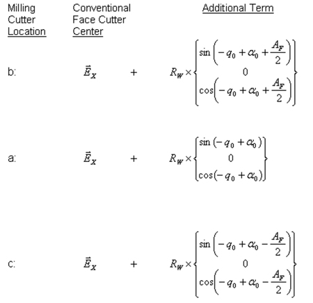
The offset vector is identical to the average cutter point radius vector and can be located in the center of the tooth face width (point a in Figure 4). Second, the milling tool has to follow a circular arc in the plane of the face milling cutter. Figure 4 shows the case where the face milling cutter rotational plane is identical to the plane X-Z. The conventional cutting machine setup positions the cutter center at the position of the tip of the vector Ex (Figure 4) in order to use a tapered milling cutter, the center of the cutter spindle has to be positioned along the path of the arc b-a-c in Figure 4 and also move between the positions b-a-c (and reverse), while the cutting machine is in one roll position. In the next roll position the movement along b-a-c has to repeat. It is also possible to use a continuous slow roll motion, while the machine axes perform a fast pendulum motion of the tool center between b-a-c. The cycle described can utilize a standard free form cutting machine with a standard cutting cycle. The only change vs. the conventional part program is the additional term shown in the formulas:

In order to generate the profile of a tooth, the generating gear has to rotate. This rotation is equal to a rotation of the vector Ex in Figure 4 about the axis Y (perpendicular to the drawing plane). The introduced new process is called “UNIMILL™”. It can be performed on a regular free form bevel gear cutting machine. The infrastructure and accuracy level of the free form bevel gear machine are a desirable platform for bevel gear cutting with the UNIMILL process. One advantage of the UNIMILL method is the fact that it produces identical bevel gear geometries as produced with face milling cutters.
Even the generating flats have the same characteristics and angular orientation between the inventive method and the face milling cutter method. Figure 5 shows to the left a three dimensional representation of the conical milling tool as it simulates the face cutter in one instantaneous roll position. Since the face cutter would produce in this roll position one generating flat per flank (indicated on the outside silhouette in Figure 5), the tapered milling tool will produce the identical flat. As the rolling motion progresses, further flats will be produced. Figure 5 shows to the right how the generating flat sections of the tool silhouette relate to the real generating flats on a flank surface.

The generating flat orientation of the 5-axis methods E are different to the face milling cutter method, which will introduce in many cased different roll conditions. The second advantage of the inventive method is the fact that standard cycles can be applied (super-imposed by said pendulum motion) e.g. for soft cutting which leads to manufacturing times of 10 to 100 times that of the processes A and D, which is in most cases only 10% of the manufacturing time of a 5-axis machine using an end mill according to process E. At the same time, the gear accuracy of the inventive method is comparable to the process A and D due to the use of a gear machine tool concept.

A third advantage of the UNIMILL method is the unlimited compatibility to the cutting and grinding with face cutters. All existing design and optimization computer programs can be used. Also the nominal data calculations, correction matrixes, are established and well proven correction software (G-AGE) can be applied without limitation.
Even in cased of unequal inside and outside blade angles of the analogue face cutter process, a tapered milling cutter with half the included blade angles (αIB+ αOB)/2 as cone angle can be used if the milling tool will be inclined by κmill-tool =-(αIB+ αOB)/2.
The calculation of the position of a tapered milling tool in the general case can be calculated, based on the geometric relationships of Figure 6 and Figure 7 as follows:

Input:
-Cutter tilt = Wx
-Cutter swivel = Wy
-Mean cutter radius = Rw
-Cutter phase angle reference value = αο
-Cutter phase angle = αx
-Roll position = q
-Blade reference height = HR
-Sliding base position = XB –
Additional milling tool inclination = κMill_Tool
-Radial Setting = S
-Cutter Radius vector at reference position = Rw(α0)

After performing the transformations from conventional basic settings to the settings of a tapered mill cutting tool the following steps can be applied in order to prepare all data for the UMIMILL process:
Chose a number of roll positions that split qstart and qend e.g. in 50 increments:
→ q1, q2, q3 … q51
where: q1 = qstart ; q2 = qstart + Δq ; q3 = qstart + 2Δq ; q51 = qstart + 50
Δq Δq =>Δq = (qend – qstart)/50
Apply for each roll position the formulas for the tool position, e.g. for 200 increments:
→ α1, α2, α3 … α201
where: α1 = α0 – AF/2 ; α2 = α1 + Δα ; α3 = α1 + 2Δα ; α201 = α1 + 200Δα
Δα = AF/200

Data Processing for Generation and Swing Motion
The described method was shown and explained for the single indexing process. It can also be applied to the continuous indexing process. The cutter rotation ω is in a timed relationship to the work rotation, superimposed to the roll motion on the work (in a continuous mode) or applied in discrete roll positions, similar to the previous explanations, where either roll and cutter rotation angle (equal tapered mill position) have been observed in discrete increments:
ωwork = ΩCradle/RA + ω ZTool/ZWork
or
δwork,i,j= δwork,start + qi/RA + αjZtool/Zwork

However, the discrete observation and processing of the roll positions lead to a looped data and position processing:
Roll position loop, q = qi , i = 1 to 51
I
I Calculating current Ex and Ycut as function of qi
I
I Cutter phase angle loop, α = αj, j = 1 to 201
I I
I I Calculate current Rw and Ycutmill as function of qi and αj
I I
I Continue next phase angle increment
I
Continue next roll position
In both cases, continuous or single index machining, the last presented formulas are valid and can be applied. Those formulas can be applied in case of an asymmetrical cutting channel (Figure 6) as well as for a symmetrical cutting channel (Figure 2). The symmetrical cutting channel only presents a special case of the more general asymmetrical cutting channel (κmill_tool = 0).
There are a multitude of possibilities to derive the formulas in order to position and move the tapered milling tool. However, trigonometric calculations would in their solution show intrinsic function depending on roll, tool rotation, and work rotation angles as well as linear constants. The derivations shown here use the basic machine settings, which relate to the generating gear. The resulting vectors Exmill and Ycutmill can be converted to basic settings:
Si = V Exx2 + Exz2
qi = arctan(Exx/Exz)
XB,i = Exy
Wx,i = arccos(Ycutmill,y)
Wy,i = arctan(Ycutmill,x / Ycutmill,z) – qi
Additional basic settings, such as:
XP
EM
γM
RA
do not change during the conversion from conventional tool to tapered mill. The basic settings, as shown above can be converted into a 6-axes Phoenix® coordinate system.
Expanding to a Variety of Highly Efficient Tools
The UNIMILL machining method can be expanded to use a milling tool which is e.g. cylindrical and only machines one flank surface e.g. the outside flank like shown in Figure 8.The tool inclination angle in this case is –αOB. The maximal diameter of such a tool is limited as shown in Figure 8. A diameter larger than shown in Figure 8 causes mutilation of the opposite flank (inside flank). It is possible with such a cylindrical tool to machine the opposite flank in a second set of machining passes, if the sign of the tool inclination angle is changed (+αOB). For correct definition it should be stated, that the vector RW2 points to the centerline of the reference profile. Its preferred location is in the center of the tooth, in case of asymmetric pressure angles it is located radial in order to split the point width of the reference profile in two equal parts. The point width is the width of the bottom of the reference channel, in an axial plane in case of face milling cutters, in the offset plane in case of face hobbing cutters. The milling tool can be located using different references, which has no effect on the functionality of the inventive method.
If the tool diameter is increased to a certain extent it becomes possible to machine the second flank (IB) simultaneously to the first (OB-flank—see Figure 9).

However, in order to machine a flank without mutilation, the requirement regarding the curvature radius is as follows:
ρOB Tip < ρminOB (given in Figure 9)
ρOB Flank < ρmaxOB (given in Figure 9)
ρIB Tip > ρmaxIB (not given in Figure 9)
ρIB Flank > ρminIB (not given in Figure 9)
The diameter of the cutting tool has to be increased until the axis of rotation crosses the origin ofρminOB (intersection with original cutting tool axis). In such a case, ρIB Tip = ρmaxIB and ρIB Flank > ρminIB applies (Figure 10).κmill_tool in Figure 10 is still -αOB like in Figure 8. Different angles of κmill_tool can be realized, if the axis of rotation intersects with the original tool axis in point Pρ. Pρ is determined as the origin of ρminOB. ρIB > ρmaxIB is always given in such a case. Figure 11 shows machining tool geometries based on κmill_tool =-60º, -70º and -90º.κmill_tool = -90º is an interesting special case of a peripheral tool.

In every case in Figure 11 (cases 5, 6, and 7) the vector ρminOB was constructed first.It has an intersection with the face cutter tool axis in point Pρ. The chosen milling tool inclination angle κmill_tool leads in Figure 11 to a tool axis, which crosses the face cutter tool axis in point Pρ. This leads to the smallest possible milling tool diameter which fulfills the requirements:
ρOB Tip < ρminOB (in Figure 11 ρOB Tip = ρminOB)
ρOB Flank < ρmaxOB (given in Figure 11)
ρIB Tip > ρmaxIB (given in Figure 11)
ρIB Flank > ρminIB (given in Figure 11)
Practical Experiences
If UNIMILL is utilized as a prototyping method, the use of disk cutters is most productive but the use of tapered end mills requires the lowest tool investment (see Figure 12, right side and middle). Multi start fly cutters, which are similar to bevel gear chamfer cutters present certain restrictions regarding blade point width and edge radius due to the use of standard inserts (Figure 12, left side). Flared disc cutters which use custom Inserts are also available [4]. The advantage of tapered end mills is the fact that most gear manufacturers can find nearby local tool shops that can manufacture a new milling tool from carbide material including coating in less than two weeks. The basic dimensions of a tapered end mill are point with, edge radius and included angle of the taper. The cutting scenario of a face hobbed hypoid pinion is shown at the left side of Figure 13.

The end mill moves from heel to toe while it is milling one generating flat at the convex pinion flank. After the end mill exits the slot at the toe, the machine axes set over to the concave side in order to machine the corresponding drive side generating flat. The movement along the face width is called “swing motion”. Changing the swing motion between start and end roll position is possible in three sections, depending on the different chip load in the different areas. After a part is finished, a coordinate measurement is conducted and in case of significant deviations between nominal and actual flank, G-AGE™ corrections are calculated and sent via network to the Phoenix® machine control.
Similar to the procedure in conventional bevel gear manufacturing, the corrections are applied in a menu to the basic settings and the UNIMILL software converts the basic settings in a part program with axes motion commands. In Figure 14 the scenario of a nose piece milling with a disk shaped HSS cutter is shown. In the case of nose pieces, disk cutters are very beneficial. The slots are normally very wide and the root fillet radius can be standardized because root bending strength is not a criteria for those parts. Today, all the UNIMILL software is implemented in the machine control. The control computer receives a download file which includes basic settings with gear blank data, very similar to regular bevel gear machining. The operator screen allows to enter speeds and feeds, as well as the number of generating flats and over travel amounts etc.
A variety of different parts, manufactured with UNIMILL is shown in Figure 15. In addition to spiral bevel and hypoid gears, milling of straight bevel gears has also been developed and tested. In case of straight bevel gears, in addition to prototype manufacturing, the possibility of machining parts with a front bearing hub is attractive for the manufacturer. Those parts have been manufactured in the past with two tool generators, which only deliver medium quality in a rather slow process. Often, the material of solid parts with integrated front hub is difficult to machine because of a high strength requirement. The possibility to use coated carbide tools in UNIMILL gives manufacturers an incentive to replace their aged two tool generators with modern CNC equipment allowing for a state of the art closed loop manufacturing. The straight bevel gear in Figure 15 requires a manufacturing time of 2 hours with a tool life of 8 parts. The tools can be re-sharpened up to 10 times until they have to be replaced.

Summary
UNIMILL is a milling method for the manufacture of prototype bevel gears using end mills or disk cutters. The UNIMILL software requires basic selling in form of SPA of AAA files as an input. Additional input items like speeds and feeds, number of generating flats, over travel amounts etc. are entered into the process parameter input screen directly on the Phoenix® cutting machine. If high RPM’s are required like in case of tapered end mills, it is possible to use Phoenix® grinding machines or cutting machines with high speed spindles. In contrast to general multi axes machining which utilizes surface coordinates and normal vectors, UNIMILL does not depend on certain grid specifications and definitions about undercut and root fillet (which are difficult to obtain). UNIMILL tools follow the path of a face cutter head silhouette, while the face cutter is performing a generating (or form cutting) motion. The result is a faster process with surface finish characteristics very similar to the traditional cutting process. UNIMILL is available on all PhoenixII cutting and grinding machines as well as on all later models.
Literature
[1] Tsuji, I. Validation and Effectiveness of Machining the Teeth of large Size Gear Pairs with Intersecting Axes using a Machining Center Dissertation, University of Tokyo, 2014
[2] Jaster, M. The latest in Big Gear Machining with DMG/Mori Seiki Gear Technology, Jan./Feb. 2012, Pages 42-44
[3] Stadtfeld, H.J. Handbook of Bevel and Hypoid Gears – Calculation, Manufacturing and Optimization Rochester Institute of Technology, Rochester, New York 1993
[4] Wermeister, G. Milling Tools for Bevel Gears Gear Solutions, April, 2011, Pages 48-52


