


The application of electrolytic metal removal technology to medium through high volume production in automotive, aerospace, medical, computer, and other markets has continued to expand as advancements are made in the technology. The process is characterized by very fast metal removal rates and the ability to focus the process on only those edges or surfaces to be finished. Deburring multiple intersections on manifolds, radiusing edges in flow control components, finishing surfaces and edges to less than 10 micro inch (0.25 micron) Ra or better, and burr-free machining of edges and features from microns to centimeters are presented. Diesel engine fuel supply components, computer disc drive hardware, and orthopedic implants are some of the current applications. Materials for these applications range from aluminum to steel to special alloys such as cobalt-chrome.
The electrolytic process uses electrodes to direct the current to the material removal site on the workpiece. Electrolyte, consisting of salts in an aqueous solution, is the electrolytic medium that is forced to flow between the electrode and workpiece surface. Direct current power, in the form of controlled pulses or constant current, provides the energy for high rate electrolytic material removal. Choosing the correct set of parameters for these applications is the key to a successful production implementation of the process. The influence of material hardness, grain structure, and geometry on the material removal results are described relative to achieving desired objectives.
Requirements for tool design for specific applications are described. The features and benefits—as well as the limitations—of the process are reviewed. The process and equipment are described and a variety of examples of successful manufacturing applications are presented.
The Electrolytic Process
Electrolytic machining is controlled metal removal via electrolytic dissolution which usually requires a shaped conductive tool to form a small gap (0.025 to 0.75 mm) between the tool surface and the workpiece; flowing conductive electrolyte in the gap; and allowing a DC current to flow between the two adjacent surfaces. The conductivity of the electrolyte solution allows electric current from a five to 30 volt DC power source to flow between the tool and workpiece. A typical electrolyte used in this process is a conductive salt solution such as sodium chloride (table salt) and water. The resulting electrical conduction within the solution is possible because dissolution in water breaks down the molecular restraining forces so that the ions, called cations (Na+) and anions (Cl-), are free to move through the electrolytic solution. Application of an electric field causes migration of one ion species with respect to the other. Since each ion carries a charge, this movement constitutes an electric current.
The passage of current through the electrolyte permits chemical reactions to occur at the electrodes (anode/workpiece and the cathode/tool). At the anode or workpiece surface, metal (M with a valence of n) dissolves and releases electrons (e- ) according to the reaction: M → Mn+ + ne–
The reaction at the cathode is typically electrolysis of water according to the reaction: nH2O + ne– → 0.5 H2 + nOH–

In the electrolyte, the dissolved metal combines with the hydroxyl ions (OH–) to form metal hydroxides which typically are not soluble in the electrolyte solution allowing filtration or precipitation to be used to remove them: Mn+ + nOH– → M(OH)n
The net reaction is therefore: M + nH2O → M(OH)n ↓+0.5n H2↑
Electrolytic current flow will cause atoms to be removed from targeted areas on the workpiece only and enter the electrolyte solution. The metal ions quickly form neutral metal hydroxides that are filtered from the recirculating electrolyte stream. Quick removal of metal hydroxides, small bubbles from the hydrolysis of water, and heat from the gap by the electrolyte permits high removal rates. The process is diagrammed in Figure 1.
The electrolytic process is usually characterized as a high rate metal dissolution process when used to remove material from designated areas on the workpiece. The material to be removed can be an unwanted burr, excess edge material, surface roughness, or a feature to be machined into the surface. The tooling and machine configuration required for these operations will be different with the system components and parameters typically chosen from an established set of constraints.

Material removal rate for ECM is essentially independent of material hardness but can be affected by alloy composition and grain size of the material. A general rule of thumb for ECM removal rate is that a tenth of a cubic inch (0.1 in3) of material is removed per minute per 1000 ampere current flow. The theoretical removal rate can be calculated based on Faraday’s law; for example, nickel has a theoretical removal rate of 0.129 in3/min., aluminum 0.126, chromium 0.137, and iron 0.135. Due to the complex nature of the activity in the machining gap, limitations of the actual machining rate exist.
The factors influencing the ECM process include the electrochemical properties of both the workpiece material and electrolyte. Other aspects include component geometry, process parameters, the tooling, and machine characteristics. These influences on the machining results are diagrammed in Figure 2.
Balancing the parameters provides an equilibrium electrochemical action responsible for the material removal results. These parameters are programmed and automatically controlled in production machines.

Electrolytic Burr Removal
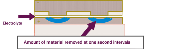
Electrolytic deburring is a targeted metal dissolution process that uses stationary tooling to focus a deburring current on only those areas where burrs are to be removed. Since the deburring tooling, known as a cathode, never touches the workpiece, there is virtually no tool wear in the process. Typical deburring times are extremely fast (10-30 seconds for most applications, see Figure 3). Depending on production requirements and the workpiece size, multiple part fixturing is used to obtain high production rates.
Typical Edge Finishing Applications
Components requiring an edge radius from hundredths of an inch to less than a thousandth of an inch are excellent applications for the electrolytic process. Edge radii can be produced repeatedly with cycle times of 30-90 seconds.

As with all specialized deburring techniques, there are certain part configurations or requirements that make a particular method most advantageous. Some good potential electrolytic deburring applications are:
• Intersecting holes or ports
• Inaccessible or hard to reach areas
• Complicated shapes
• Areas requiring a consistent radius
• Areas which cannot be abraded
• Materials which may work harden
• Parts processed on automated lines where work flow cannot be interrupted
• Areas where large radii are required
The process requires that all grease, oil, hanging burrs, and loose chips be removed from the workpiece prior to the operation. The following examples of production applications demonstrate the range of electrolytic process capabilities including: deburring, radius forming, contouring, and surface finishing.


Gears
Critical edges are produced via electrolytic deburring and radiusing of gear teeth. Applications range from automotive transmissions to fishing equipment. The deburring and radius requirements vary depending on the application and design. Burrs can range from 0.02 to 0.2 mm. In these applications shaped cathodes are fixtured at a predetermined distance from the gear edge such that burrs are positioned in the electrolyte flow path without touching the cathode. (A short circuit detection system is used to confirm that no burrs are in contact with the cathode prior to power being applied.) Cycle times for gear deburring range from five to 30 seconds and edge radiusing times range from 15 to 90 seconds, depending on the radius requirement.
Airbag Housing Inflation Nozzles
Nozzle holes of various sizes in aluminum airbag inflator housings (canisters) require burr-free edges with a slight radius for proper performance. These housings are made of 6061 T6 aluminum, approximately 64 mm diameter, 250 mm long with a wall thickness of 3 mm and typically have from 20 to 60 holes with burrs generated on the ID surface by drilling or piercing operations.

The electrolytic tooling is configured to simultaneously deburr all holes in one operation to achieve the shortest cycle time. The tolerance of hole position and the dimensions of burrs to be removed influences both tool design and machining parameters.
The cathode tools for this application have insulated surfaces with exposed conductive surfaces adjacent to each deburring site. The size of each conductive cathode surface is dimensioned to encompass the burr over the tolerance range of hole position.
The machining parameters are set based on the volume of burr material to be removed, the interelectrode gap, and the electrolyte characteristics. For example, the time required to remove all burrs could increase from 10 to 20 seconds if the amount of burr material increases as indicated in the time plot of Figure 3. Typical machining parameters are:
|
Voltage:
|
18 V
|
|---|---|
| Current: | 150 A |
| Electrolyte: | NaNo3 |
| Electrolyte parameters: | 25 C |
| 8.0 pH | |
| 1.5 bar |
Valve Body
Intersecting holes requiring burr free or radiused intersections are among the typical applications for this process. The requirement is to remove all burrs from seats and intersections. These valve housings are usually deburred in three setups. Each process step is approximately 15 to 20 seconds.
Fuel System Components
Fuel system components that require burr-free radiused edges at intersections are good examples of electrolytic deburring and radiusing applications. In this example other features such as edge contouring are also produced electrolytically in one operation.
Other fuel system components that rely on the electrolytic process include fuel rails with intersections requiring 0.75 to 1.5 mm radius and injector nozzles for diesel engines that require a fuel accumulation chamber (referred to as a gallery) in the main bore. A gallery is a burr-free and stress-free undercut of precise volume machined into the plunger bore. The gallery is electrolytically machined with a stationary tool that produces an increasing volume as the machining gap widens. In this application a constant current power source is used to produce an accurate volume. Electrolytic machining time is typically less than two minutes.

Projectile Tail Cone
A tail cone for a 120mm projectile made from an H-13 steel forging has critical edge requirements that are produced electrochemically. Nine holes are gun drilled at a slight angle to the major axis then internal and external conical surfaces are turned.
The nine gun drilled holes that form an obtuse to acute angle intersecting the interior and exterior conical surfaces require deburring and a radius formed that varies according to the angle of intersection. Approximately one millimeter of material must be removed from the exterior acute angle to generate 1.25mm radius. The exterior requirements are achieved in a 2.5 minute cycle with the cathode advancing toward the workpiece parallel to the axis of the cone.
The interior intersections are deburred and radiused in 1.5 minutes with fixed position cathodes. Shorter times for the latter is due to the small, consistent burr on these edges.

Electrolytic Polishing
Electrolytic Polishing — or Electrochemical Polishing (ECP) — is a process of applying conventional electrochemical machining methodology to improving surface finish of metals, primarily high chrome materials such as stainless steel. The process is orders of magnitude faster than Electropolishing (EP) and can remove very rough surface conditions while also brightening (improving the reflectivity of) a surface. In contrast to EP, which is a bath process, ECP is a fixtured process requiring small spacing between tool and workpiece with constant flow of electrolyte. The process does not use acid electrolytes, and therefore does not have the same environmental or operational concerns as electropolishing. The salts used in the ECP electrolyte are generally very easy to handle and store (table salt is one of the common electrolytes). The ECP process has many excellent applications, but is not a universal substitute for EP. The potential applications are estimated to be between 10 and 20 percent of EP applications, and most of those will not only replace the EP step but will also replace the surface roughness improvement step done prior to EP.
Electrolytic polishing is a process of surface roughness reduction that is usually accompanied by surface brightening. A typical arrangement for polishing a surface is depicted in Figure 4. The cathode tool is held a small distance from the workpiece surface. The distance is typically in the range of 0.7 mm. As a result of this requirement, the tool must be shaped similar to the surface to be polished.

tooling example
The electrolyte required for the current flow is pumped through the tool in this example. The current flow “smoothes” the surface by a “deplating” action that removes material from the peaks of the surface roughness at a rate slightly higher than the material from the valleys. This results in an overall material removal from the surface on the order of 0.01 to 0.02 inch to improve a surface roughness by a factor of 10. Figure 5 is a “before and after” trace on a stainless steel component polished from 73 micro inch Ra to less than 10 micro inch Ra in three minutes.
Electrochemical Metal Removal Rates
In polishing applications the best surface finish attainable is limited by the constituents of the material and the grain structure. The optimum result on a workpiece will primarily be determined by the electrolyte used and the current density achieved during the polishing operation.
Cathode (Tool) for ECP
Brass, stainless steel, or copper tungsten is used for electrodes. Tooling tends to be robust, and cathode tools do not wear or dissolve in the process which eliminates the need for frequent, costly tool replacement encountered with many other processes.
The tooling, which consists of cathodes and a part fixture, are extremely important parts of the ECM system. The configuration of the cathode and the electrolyte flow arrangement are responsible for the polishing results. Keeping in mind that a dynamic gap exists between the tool (cathode) and workpiece, the design of these components will determine the resulting quality and accuracy of the process. Adequate anode current contact must also be provided in the fixture. The materials used for cathodes and fixture are critical to the performance of the process. It was noted earlier that cathodes are typically made of brass. In some EDM recast removal applications, however, the EDM electrode can be used if the workpiece was orbitally EDM’d. In these instances the electrode is undersized, which will allow for the gap required during EC polishing (when properly fixtured).
Some of the earliest production installations of ECP were in Germany and East Europe. These applications were polishing die cast molds after EDM machining. For example, an aluminum casting die for an automotive transmission was polished in 15 minutes after EDM.

control elements
Valve Housing
Surface finishes as rough as 200 to 300 micro inch Ra on machined internal surfaces of 316 stainless steel valve bodies are electrolytically smoothed to an eight to 16 micro inch Ra in a very short process cycle. The resulting finish is smooth, bright, and similar in characteristic to an electropolished surface.
Die Mold (Open Cavity)
ECP is also used to remove 80 to 90 percent of recast material from molds for glass and aluminum.
Surgical Component
Removal of EDM and laser recast layer is often accomplished by electrolytic removal because of the selectivity possible with the process and the stress-free method of material removal.
Typically 0.01 to 0.05 mm of surface material is removed which is determined by the EDM or laser process parameters that produced the Martensitic “recast” layer.
Blade Tip Machining
Jet engine blades that are designed to self-seat while rotating inside a machinable shroud are manufactured with abrasive particles bonded to the blade tip. The abrasive particles, which are imbedded in a metal binder, must protrude from the blade tip by 0.15 to 0.25mm. The electrolytic process is used to remove metal binder from the blade tip exposing the non-conductive abrasive grains. The excellent repeatability and fast metal removal rate results in a high quality, productive operation. This operation uses low electrolyte flow rates and a large gap. An adjustable head permits quick set up for different blade lengths.
microECM Applications
The microECM process can produce features a few microns deep by tens to hundreds of microns wide. In general, the process is limited by the ability to produce the cathode tool required to machine the desired features.
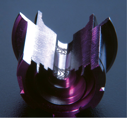
An example of microECM is machining of grooves for fluid dynamic bearings (FDBs). Fluid bearing grooves have been produced by the ECM process since the 1960s. The fluid dynamic bearing grooves in this example, however, are several orders of magnitude smaller. Within the last year new FDB computer disc drive motors have been replacing ball bearing motors. These new motors are quieter, more robust, and less expensive. The typical requirement for FDB performance is a pattern of grooves on internal stator surfaces (Figure 6) and thrust bearings ( Figure 7). The grooves shown in Figure 6 are approximately 10 microns deep and less than 100 microns wide. In this example there are 64 “V” shaped grooves on a 5 mm bore. All 64 grooves are simultaneously machined with one microECM cathode in under three seconds. The normal depth tolerance for these grooves is ± 1 micron (i.e. ±10 percent). To date, more than 200 million FDB motor disc drives have been manufactured.
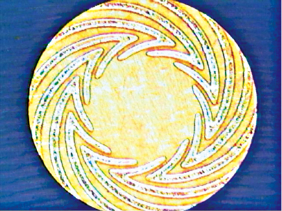
The thrust bearing of Figure 7 is microECM’d in a similar manner. All groves on the thrust plate surface are machined in a two second machining operation. The microECM cathode configuration for groove machining in FDBs is shown in Figure 8.
microECM Groove Machining
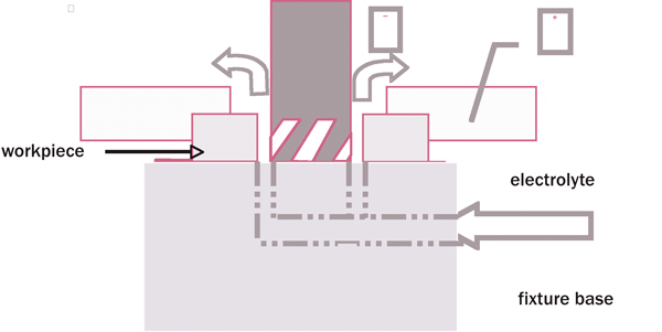
As pulsed current flow occurs between cathode face and workpiece, material is removed, atom by atom, in the areas adjacent to the cathode face. The narrow gap minimizes the “overmachining.” Figure 9 shows how a workpiece would be microECM’d with internal groove features. A typical process time for microECM is two to 10 seconds, and multiple parts are often machined simultaneously.
Flow Tuning
Precision flow requirements for nozzles and orifice holes can be achieved with electrolytic flow tuning. The electrolytic material removal process precisely machines flow orifices by uniformly shaping the walls and/or edges of the flow surfaces through electrolytic dissolution while flowing electrolyte at precisely controlled pressure and flow rates; i.e. under dynamic flow conditions.
High pressure precision flow requirements in diesel fuel system components are one example of applications for this capability. Other applications in medical and aerospace will benefit as well.
Overview of Production Systems
Production equipment consists of five elements, listed as follows:
• Machine
• Control
• Power Supply
• Electrolyte System
• Tooling
Each of the elements is selected to provide the required process control. A schematic of a production system showing the process control elements generally required for consistent results are shown in Figure 10.
Electrolytic Equipment
Electrolytic process production machines are used in conjunction with tooling designed to suit specific workpiece geometry. The machine is constructed of stainless steel, with separate compartments for the electrolyte reservoir, power supply, and control circuits.
The equipment design for the electrolytic process is largely influenced by the workpiece to be processed. The dimensions of the workpiece, the production rate, and quantity of material removal will determine whether a single station, dual station, or a special fully automatic machine is required. Machines may also be equipped with indexing tables locating devices or other special configurations for workpiece manipulation. Some fully automated systems will also have integrated parts washing systems. Small open machines have provisions for tools to be mounted over an electrolyte drain basin.
Tooling configurations for these machines typically consist of an upper platen that holds anode contacts, part clamping points, and electrolyte sealing surfaces. A lower platen holds a workpiece fixture, cathodes, and electrolyte connections.
Conclusion
Electrolytic material removal technology has improved and expanded applications as a result of advances in pulse machining and electrolyte management. Medium through high volume production applications in automotive, aerospace, medical, computer, and other markets has continued to expand as advancements are made.
The process is characterized by very fast metal removal rates and the ability to focus the process on only those edges or surfaces to be finished. Edge finishing, polishing, and micro machining are some of the examples that demonstrate the range of capabilities of the process. Larger radius requirements in higher pressure fuel components for diesel engines and more cost effective finishing of valves for food, pharmaceutical, and semiconductor applications are some of the reasons for the increased use of electrolytic machining processes. New applications such as micro machining and flow tuning are also expanding the technology into high precision, high volume production applications.
References
• Datta, M. and Landolt, D., 1981, Electrochemical Machining Under Pulsed Current Conditions, Electrchemica Acta, 26/7: 899-907.
• Konig, W. and Humbs, H.H., 1977, Mathematical Model for the Calculation of the Contour of the Anode in Electrochemical Machining, Annals of the CIRP, 26/1: 83-86.
• Kozak, J., Lubbkowski, K., and Mahbound, A., 1989, Characteristics of Pulse Electrochemical Machining, Proc. Of ASME Winter Annual Meeting, PED-Vol.34: 189-197.
• McGeough, J.A., 1974, Principles of Electrochemical Machining, Chapman and Hall, London.
• Rajurkar, K.P., Kozak, J., and Wei B., and McGeough, J.A. 1993, Study of Pulse Electrochemical Machining Characteristics, Annals of the CIRP, Vol. 42/1: 231-234.


