


By Dr. A.L. Kapelevich and Dr. Y.V. Shekhtman
The Direct Gear Design method optimizes various parameters and elements of gear tooth geometry to achieve the required gear drive performance. One such critical element of the tooth profile is the root fillet. Its optimization by means of Direct Gear Design provides the ultimate bending stress minimization. Previous publications [1, 3] described the tooth root fillet optimization assuming that both mating gears have a solid body.
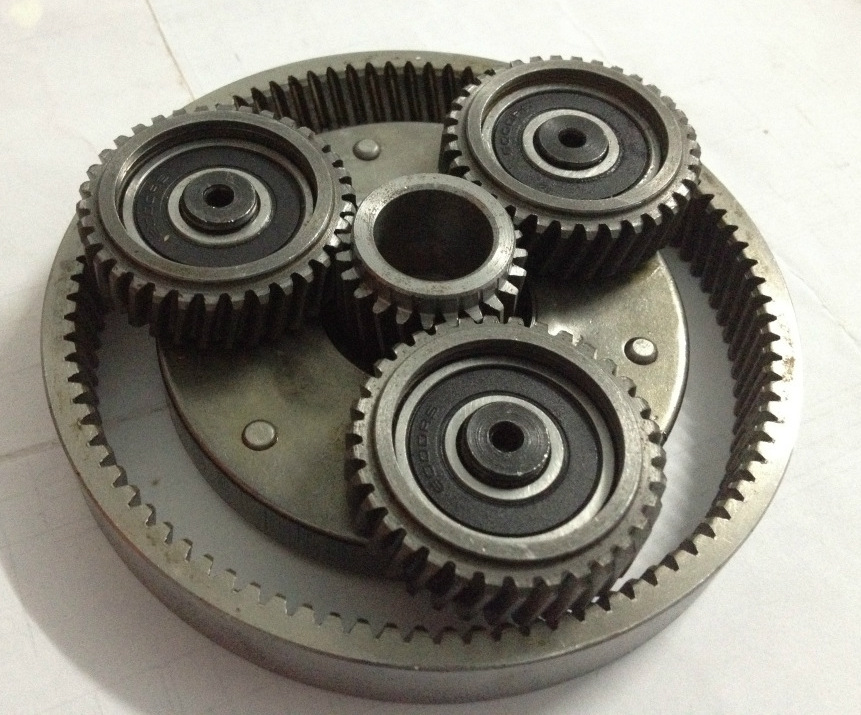
Application of asymmetric gears allows maximized power density of an epicyclic unidirectional gear stage, usually reducing a gear drive size. This means a reduction of a center distance and all gear dimensions, including the planet gear root diameter. In many cases a planet gear is supported by a roller bearing incorporated inside the gear using its inner diameter as a roller bearing outer race surface (see Figure 1). A reduction of the center distance, while the transmitted torque remains constant, increases planet gear roller bearing load. It leads to the necessity of increasing a diameter of the roller bearing to maintain its required load capacity and life. A simultaneous reduction of the planet gear root diameter and increase of its inner diameter significantly reduces the planet gear rim thickness, increasing the tooth root bending stress. In such cases, a tooth root fillet optimization is essential to keep root stresses within an acceptable level.
In an epicyclic gear stage, a planet gear transmits the same torque by both tooth flanks. However, the convex planet gear tooth flanks are in simultaneous meshes with the convex sun gear tooth flanks and the concave ring gear tooth flanks. As a result, contact stress in the sun-planet gear mesh is much greater than in the planet-ring gear mesh. The application of asymmetric tooth gears in an epicyclic stage allows one to equalize the contact stresses by choosing a greater pressure angle in the sun-planet gear mesh than in the planet-ring gear mesh, and by optimizing the asymmetry factor [2] in order to maximize load capacity. The sun-planet gear engagement loading is selected for the root fillet optimization, because it results in a greater stress in the planet gear tooth root compared to the planet-ring gear engagement loading.
This paper describes the analysis and optimization of the tooth root fillet in thin rim planet gears with asymmetric teeth, while also defining the location of the bearing roller relative to the planet gear tooth that causes maximum root stress. A comparison is also made of the optimized root fillet shapes and corresponding maximum bending stresses of planet gears with different values of rim thickness.
Tooth Root Fillet Optimization Approach
In Direct Gear Design [3], the tooth fillet is constructed after the involute flank parameters are completely defined. The goal is to achieve minimal stress concentration in the tooth fillet profile. As a result, the maximum bending stress is evenly distributed along a large portion of the fillet. Furthermore, the optimized root fillet must not interfere with the mating gear tooth tip. The root fillet optimization method, developed by Dr. Y.V. Shekhtman, uses three major procedures: the definition of functions for fillet profile approximation; FEA for stress calculation; and a random search algorithm to define the optimal set of coefficients for the trigonometric functions, allowing them to reach minimum bending stress. It is described in detail in [1].
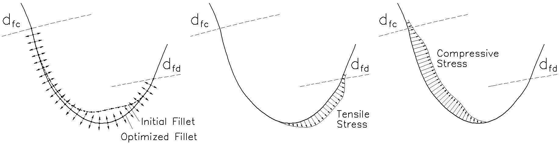
Prior to optimization, the initial tooth root fillet profile (Figure 2a) is a trajectory on the mating gear tooth tip in a backlash-less engagement. Finite element nodes are evenly distributed along the initial root fillet profile. The first and last finite element nodes of the initial fillet profile, located on the form diameter circles, cannot be moved during the optimization process. The rest of the finite element nodes are moved along straight lines perpendicular to the fillet profile. Bending stresses are calculated for every iteration of the fillet profile configuration. A new position is defined for each finite element node based on the results of the previous iterations in order to reduce stress values. After achieving a maximum value for the root fillet stress that cannot be further reduced, the optimization process stops. The optimized fillet profile provides even stress distribution along a significant length of the stretched (Figure 2b) and compressed (Figure 2c) portions of the root fillet.
Thin Rim Planet Gear FEA Modeling
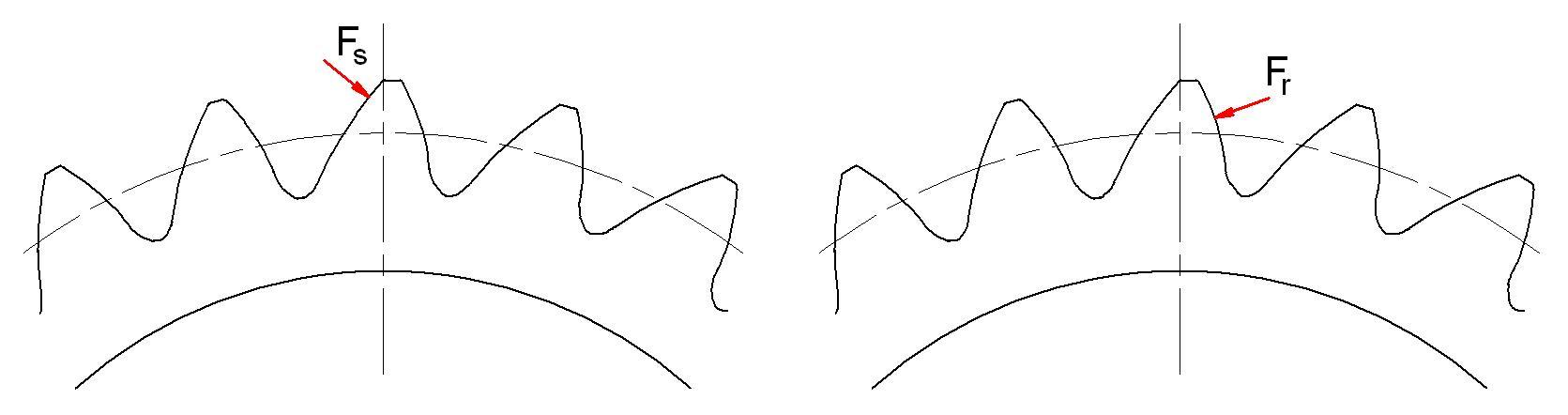
The planet gear tooth flanks are loaded by the normal forces Fs applied from the sun gear and Fr applied from the ring gear (see Figure 3).
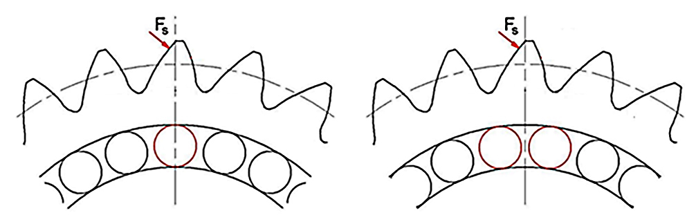
The thin rim planet gear’s maximum root stress value varies depending on the supporting bearing rollers’ position (Figure 4). Two roller positions are considered: when the gear tooth is in line with a roller (Figure 4a) and when the tooth is between two rollers (Figure 4b).
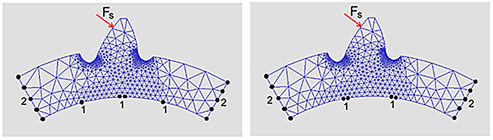
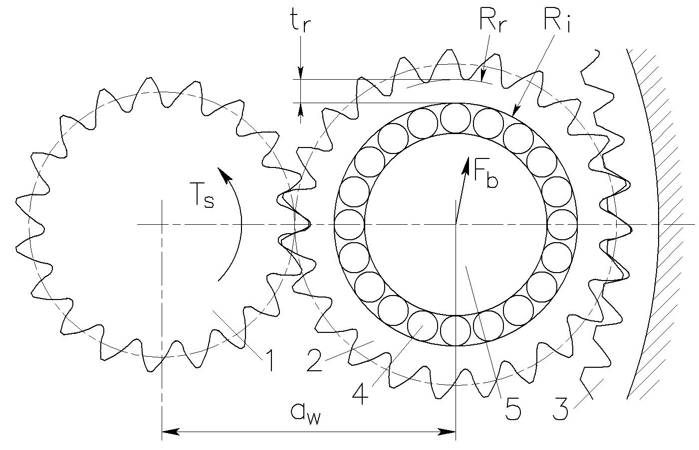
The finite element model’s constraint conditions reflect the bearing rollers positions (Figure 5). FE nodes 1 represent the bearing roller contact points with the planet inner circle. They are radially constrained, but have freedom to move along the inner circle. FE nodes 2 at the left and right ends of the model are constrained in the tangent direction, but they have freedom to move in the radial direction.
Thin Rim Planet Gear Root Fillet Optimization
The thin rim planet gear’s stress isograms and stress charts along the tooth profile are shown in Figure 6. The tooth root fillet is optimized assuming the sun gear load is applied to the high pressure angle tooth flank (Figure 6a). This allows one to reduce the maximum bending stress for tooth load applied both from the sun and the ring gears (Figure 6b).
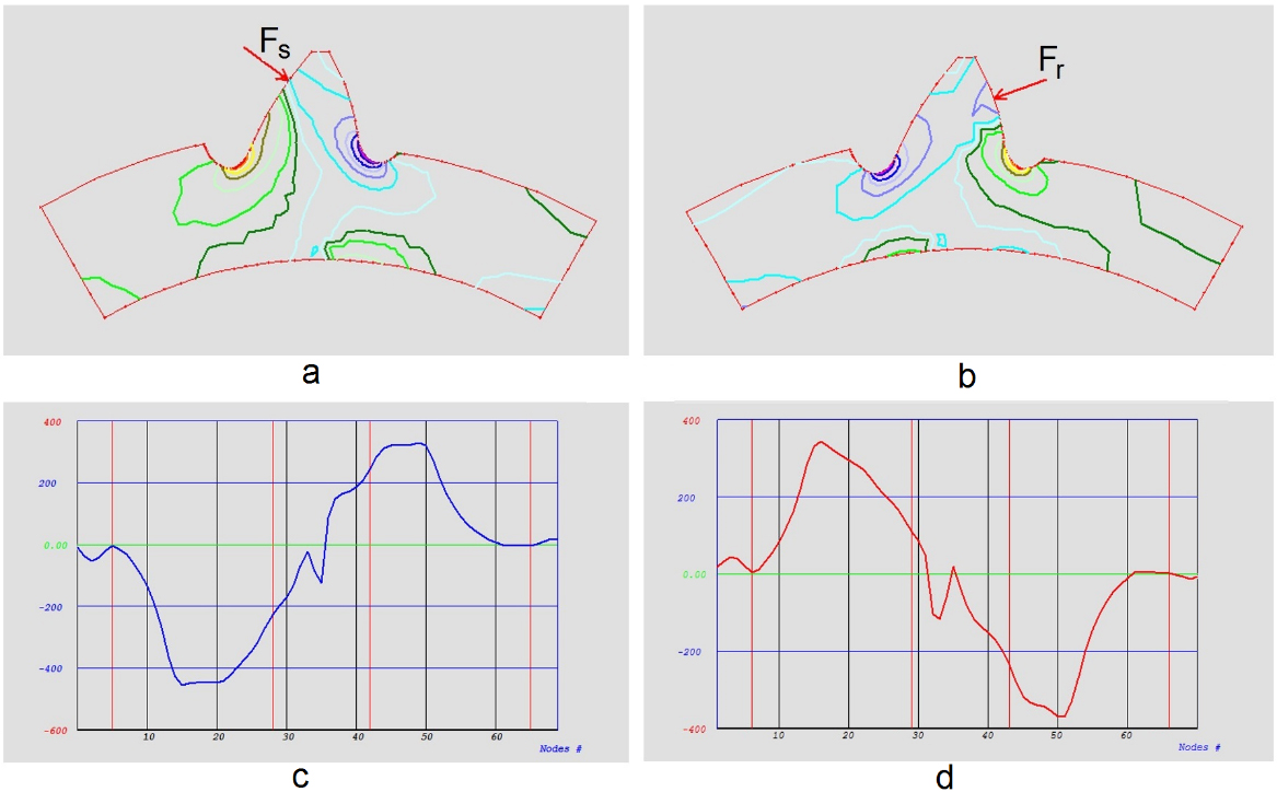
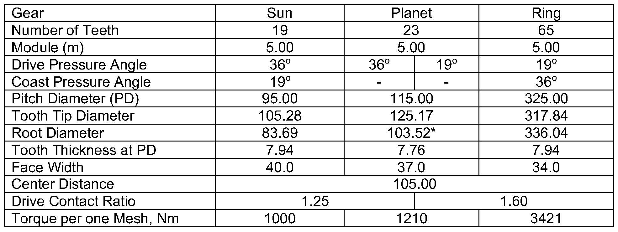
Table 1 presents geometric data and load conditions for an epicyclic gear stage with asymmetric tooth gears. The optimized planet gear root fillet stresses and shapes were studied accounting for different rim thickness values.
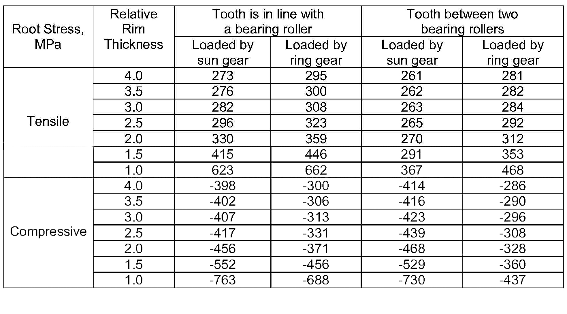
Max. planet gear root stress values for different bearing roller positions, load applications, and rim tooth thickness values are presented in Table 2.
The planet gear tooth root stress-rim thickness chart is shown in Figure 7.
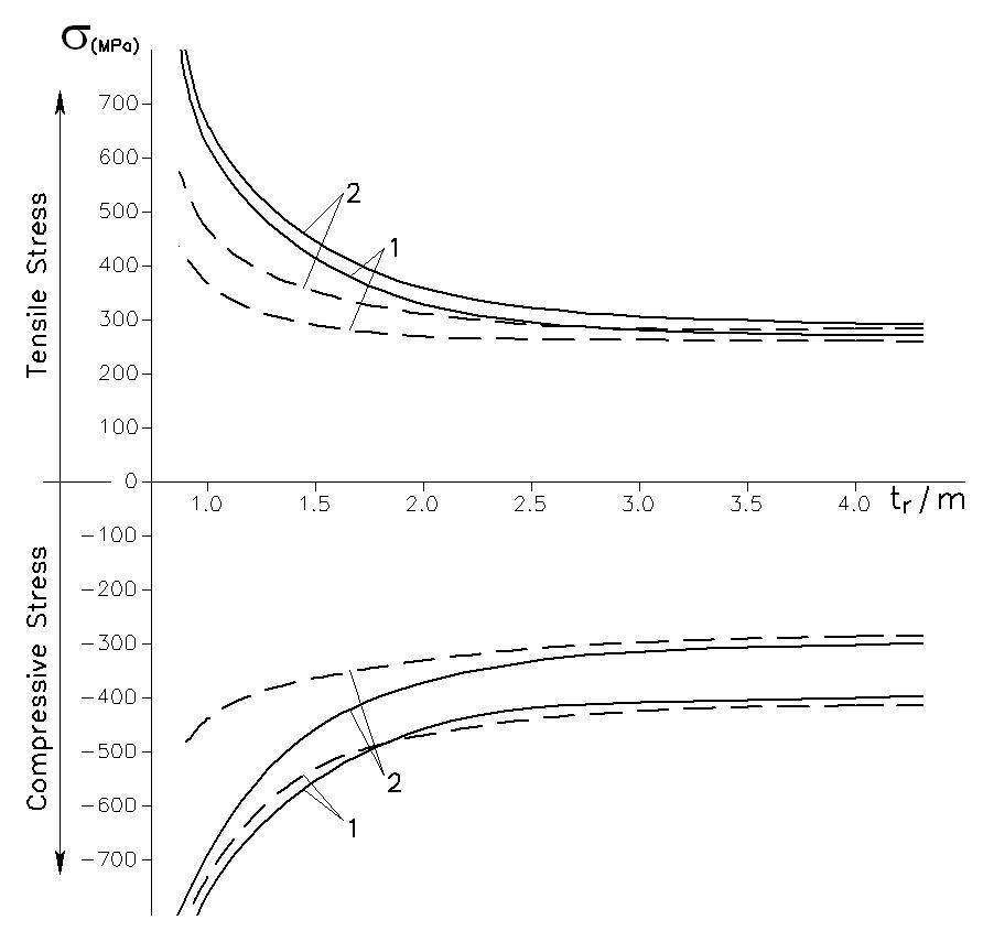
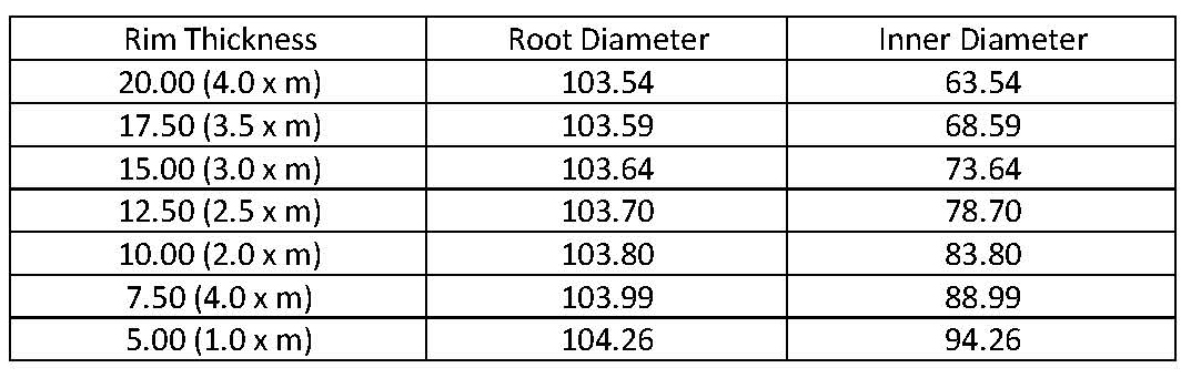
This chart and Table 2 indicate that if the rim thickness is greater than 3.5 x module, tooth root stresses do not depend on the rim thickness and are practically the same as for solid body planet gears. If rim thickness is less than 3.5 x module, tooth root stresses greatly depend on the rim thickness. They grow exponentially as rim thickness is reduced. Table 3 shows how the planet gear root and inner diameters depend on rim thickness when the tooth root fillet is optimized.
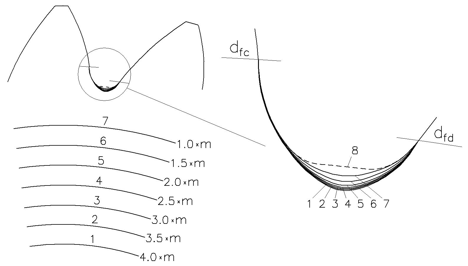
Figure 8 demonstrates the optimized tooth root fillet profiles and inner diameters of the planet gear depending on rim thickness.
Summary
This paper describes the analysis and optimization of the tooth root fillet of thin rim planet gears with asymmetric teeth. The sun-planet gear engagement loading is selected for the root fillet optimization, because it produces a greater normal tooth force applied closer to the tooth tip in comparison to the planet-ring gear engagement loading. A tooth position in line with a bearing roller is chosen for root fillet optimization, because in this case the root stress is greater than if the tooth is located between two rollers. If the rim thickness is greater than 3.5 x module, tooth root stresses do not depend on the rim thickness. If the rim thickness is less than 3.5 x module, tooth root stresses grow exponentially as rim thickness is reduced. An application with a rim thickness that is less than 2.0 x module leads to a significant increase in planet tooth root stresses and is typically not recommended. The thinner the planet gear rim, the more its root diameter is defined by the optimized root fillet. This also reduces the root radial clearance, which could be undesirable for some applications.
References
- A.L. Kapelevich, Y. V. Shekhtman. Tooth Fillet Profile Optimization for Gears with Symmetric and Asymmetric Teeth, Gear Technology, September/October, 2009, 73 – 79.
- A.L. Kapelevich, Asymmetric Gears: Parameter Selection Approach, Gear Technology, June/July, 2012, 48 – 51.
- A.L. Kapelevich, Direct Gear Design, CRC Press, 2013.
About the authors Dr. A.L. Kapelevich and Dr. Y.V. Shekhtman are with AKGears, LLC, which is based in Shoreview, Minnesota. Learn more by visiting www.akgears.com.


