







When analyzing a situation, social scientists wonder, “What is the angle that this conversation is taking?” Every conversation maintains a bias whether overtly or unacknowledged. This bias is known as the “angle.”
Gearing is also driven by angles, and these values drive the very geometry that defines the gear shape and performance.
When a design engineer is suddenly tasked with specifying a gear drive for a piece of industrial equipment, the terminology can be overwhelming. There are five critical angles in gear design that must be understood to select the best design for your application: the pressure angle, the helix angle, the spiral angle, the lead angle, and the pitch cone angle. Some of these angles apply to all gearing and others apply only to specific styles of gearing.
The Pressure Angle
When looking closely at a standard gear tooth, the shape of the tooth is curved. This curve is an involute profile, and the pressure angle dictates its exact shape. The pressure angle is the angle of the line of action, the path along which the force is transmitted between two mating gears, relative to a line tangent to the pitch circles. For decades, the industry standard for the pressure angle was 14.5 degrees. Today, the 20-degree pressure angle is the universal standard for stock gearing; however, a 25-degree pressure angle is sometimes used for specific high-load applications.
The pressure angle determines the thickness of the tooth at its root. A higher pressure angle results in a wider tooth base, which significantly increases the gear’s bending strength and load-carrying capacity. However, a larger pressure angle does have drawbacks. The higher pressure angle transmits more radial force into the gear shafts. This means the shaft bearings must be sized larger to manage the increased load, and the gear mesh will generally produce more noise. Regardless of the pressure angle used, both gears in the mesh must have the exact same pressure angle to operate properly.
The Helix Angle
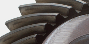
When dealing with parallel shaft orientations, spur gears are the most common choice. However, their teeth engage across the entire face simultaneously, which can cause vibration and noise at high speeds. To improve the contact area, and reduce noise, the use of helical gears is preferred. In a helical gear, the teeth are cut at an angle to the axis of rotation. This angle is the helix angle.
Because the teeth are angled, they engage gradually, starting at one end of the tooth and rolling smoothly across the face. This gradual engagement allows helical gears to run significantly smoother and quieter than spur gears. Helical gearing allows for a higher contact ratio as more than one tooth is in contact at any given time. This permits helical gears to carry higher loads.
Due to the helix angle, the tooth acts like a wedge. As power is transmitted, it generates axial thrust, a force pushing the gear horizontally along the shaft. If a design specifies helical gears, it must also specify thrust bearings in the housing to absorb the axial load. Regardless of the gears chosen, a pair of helical gears must be of opposite hands; a right-hand helical pinion can only mate with a left-hand helical gear and vise versa.
The Spiral Angle
When an application requires gears with intersecting axes, the typical choice is a pair of bevel gears. Straight tooth bevel gears are the intersecting axes equivalent of spur gears. Spiral tooth bevel gears are the intersecting axes equivalent of helical gears.
Spiral bevel gears are defined by the spiral angle. This is the angle of the curved teeth relative to the gear axis. The most common standard spiral angle is 35 degrees. Just like the helix angle, the spiral angle provides a smoother, quieter, and higher load-carrying action compared to straight bevel gears. This makes them ideal for high-speed, high-torque, right-angle drives.
With spiral bevel gearing, the thrust forces are more complex. Depending on the direction of rotation and the hand of the spiral, left-hand or right-hand, the axial thrust will either try to pull the gears into a tighter mesh or push them apart. A gearbox housing and its bearings must be rigorously designed to maintain exact alignment under these shifting forces.
The Lead Angle
For nonparallel, nonintersecting axes, where there is a need for massive speed reduction in a compact space, a worm gear pair is the best solution. The worm itself looks like a screw thread. The lead angle is the angle between that thread and a plane perpendicular to the worm’s axis. If the thread were to be unrolled from the cylinder, the lead angle would be the angle of the resulting wedge. The lead angle is the primary factor in determining the mechanical efficiency of a worm gearset as higher lead angles generally mean higher efficiency.
The lower the lead angle, the more friction the system generates. While friction is usually the enemy of mechanical design, in worm gears, it can be a feature. If the lead angle is small enough, typically under four degrees, the friction prevents the worm wheel from driving the worm in reverse. This is known as “self-locking,” and it is an invaluable characteristic for lifting mechanisms, hoists, and conveyors where the designer does not want the load to free-fall if the power cuts out.
The Pitch Cone Angle
While spur and helical gears operate on cylindrical pitch surfaces, bevel gears operate on conical pitch surfaces. Imagine two ice cream cones rolling against each other. The pitch cone angle is the angle between the center axis of the gear and the outer edge of that imaginary cone. When two bevel gears meet at a 90-degree shaft angle with a 1:1 ratio, also known as miter gears, both gears have a pitch cone angle of 45 degrees. If the speed ratio changes, then the cone angles must change proportionally so their apexes meet perfectly at the intersection of the two shafts.
This geometric reality makes bevel gears fundamentally different from spur gears. With spur gears, it is possible to mate a 20-tooth pinion with a 40-tooth, 50-tooth, or 60-tooth gear as long as the pitch and pressure angle match.
This cannot be done with bevel gears. Because the pitch cone angle is calculated based on the specific number of teeth on both mating gears, bevel gears must be designed and manufactured as matched pairs. If a 40-tooth bevel gear fails, it cannot simply be replaced with a 50-tooth gear as the pitch cone angle will be wrong, the teeth will bind, and the system will destroy itself.
Facts are irrefutable in engineering, but sometimes it takes experience to know which facts apply to a specific problem. The angles of a gear dictate not only how it looks, but the forces it creates, the noise it generates, and the bearings required to support it. When sitting down to specify power transmission components for the next project, do not just guess at the geometry.
Understand the angles, define the shaft orientations, and know the loads that need to be transmitted. And remember, there is no need to reinvent the wheel; partnering with a pure-play gear provider ensures that the right geometry for the job is designed the first time.


