





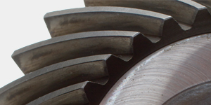


Most electric vehicles have one electric motor per driven axle, which transmits motion and torque through a single- or two-speed transmission to the wheels. Today, these transmissions require ratios between 12 and 30 and even higher in the future with smaller and higher RPM electric motors. There are two applications of bevel gears: The first as a speed reducer and final drive gears in the trans-mission and the second application is the differential unit.
Ratios are not the only different requirement between conventional and electric vehicle transmis-sions. The requirement portfolio also covers, of course, the criteria “power density,” “noise,” and “efficiency.” Electric motors can deliver short bursts of peak torques, which are several times as high as the nominal power rating. This provides the electric vehicle with a sporty touch and makes it at-tractive to certain groups of consumers. The transmissions have to be able to handle these high-peak torques during the entire vehicle life cycle.
Although, from a practical point of view, efficiency should have the highest priority right after the strength of the gears, in reality, the noise emission has been found to be of much higher priority for the customers. Due to the high RPMs of motor and gears, some vehicle owners notice strange high-pitch humming sounds they never experienced in a vehicle before. Some vehicle owners just complain that it is uncomfortable, while others claim it puts a permanent ringing in their ears that does not go away after they leave their electric cars.
 This means for electric vehicle transmissions, advanced manufacturing and gear mating technologies have to be applied. Gears have to be ground or hard-skived and honed. Combinations of a honed and a ground gear or a ground gear with a hard-skived gear have proven to deliver the lowest noise emission and are also less likely to emit high-pitch frequencies. Electric vehicle cylindrical gears will also require sophisticated topological flank surface optimizations that provide conjugate flank centers for optimal transmission characteristics as well as high load-carrying capabilities. Only the tooth boundaries in path-of-contact direction are relieved to prevent load concentration peaks under highest loads. Although hard skiving is not a common hard-finishing process for cylindrical gears, it is about to have a break-through for internal transmission rings.
These rings are not hard finished at present because grinding would require a miniature sized grinding wheel. Today, the internal teeth are finish shaped or broached and then either heat treated with the goal of low distortions or ion-nitrited. The nitriting only creates a 0.01mm hard skin on the surface, but it guarantees very low distortions. It is also possible today, with the power-skiving process, to perform a hard-finishing operation after heat treatment by applying carbide hard-skiving cutters. Noise emission and high loads also put difficult requirements on the bearings and the transmission housing design. Even the smallest vibrations can become noise problems when the vibration finds a resonance in the surrounding vehicle components.
The development of modern high-power density and low NVH (Noise, Vibration, and Harshness) differentials has been presented and discussed in [1, 2]. This article concentrates on the development of spiral bevel and hypoid gearsets with high strength and low dynamic excitation.
About high Frequency Noise from Electric Vehicle Transmissions
Due to the higher electric motor efficiency with higher RPM, electric motors as prime movers in cars rotate five to 10 times faster than internal combustion engines (10,000 RPM to 20,000 RPM). With identical wheel diameters, the ratio of an electric vehicle transmission, therefore, also needs to be five to 10 times higher. This ratio is increasing as smaller electric motors with even higher RPM are developed.
Frequencies in an electric vehicle transmission are calculated in a manner as shown in the following example: Vehicle speed of 80 km/h = 50 MPH. The motor rotates at 10,000 RPM. The transmission has two stages: the first with 13 x 40 teeth and the second stage with 15 x 49 teeth. The overall ratio is 12, which means the tires rotate with 10,000/12 = 833.33 RPM. With a tire diameter of 20 inches = 0.508 m this results in a vehicle speed of V = π • 0.508m • 833.33 RPM = 1,329.94 m/min = 80 km/h = 50 MPH (results are rounded).
The first stage of this transmission has a tooth mesh frequency of 13 pinion teeth • 10,000 RPM/(60s/min) = 2,167 Hz. The human ear can recognize frequencies between 16 Hz and 20,000 Hz. This means that even the ninth multiple of the mesh frequency (20,000 Hz/2,167 Hz = 9.23) is still audible. The second stage of the transmission has a tooth mesh frequency of 15 pinion teeth • 10,000 RPM • (13/40)/(60s/min) = 812.5 Hz. This means that, theoretically, even the 24th order harmonic mesh frequency is audible by the human ear. However, because the harmonic mesh frequencies lose energy as their order increases, in reality only the first 12 harmonic mesh frequencies are expected to be audible.
The first six orders of stage 1 will be critical in a quiet electric vehicle because the lower order frequency peaks represent the majority of the vibration energy. There are about 150 generating marks that are considered flank waviness. However, vibration and noise originated by generating marks in the first stage have frequencies of more than 325,000 Hz, which is well above the capacity of the human ear. Generating flats in the second stage have a frequency of 121,875 Hz and are also not audible.

Surface roughness generally causes first and second stage frequencies that are not audible. If waviness has a frequency between three and 12 on first stage flank surfaces, then audible noise events might occur. Pinion and gear runout in the first stage causes audible frequencies of 166 Hz and 54 Hz. Both can be recognized as a buzzing sound. Pinion and gear runout in the second stage causes frequencies of 54 Hz and 16.3 Hz, which are still audible as a very deep buzzing sound. The question is: Is high surface finish fine grinding or polishing of the flank surfaces a viable measure to reduce high frequency noise? The above study of the typically present frequencies in an electric vehicle transmission points, rather, in the direction of reducing the first 12 fundamental orders of mesh, which is only partially possible by polishing the flank surfaces. These orders are attributed to the meshing impact as well as to profile errors or multiple disturbances along the path of contact. Disturbances along the path of contact can be caused by the generating process during the hard-finishing manufacture. The later presented psychoacoustic optimizations have proven to reduce the peak amplitudes by surface modulations rather than by additional finishing processes.
Application Examples of Bevel and Hypoid Gears
There are two practical bevel gear solutions to achieve reduction ratios between 10 and 80. Figure 1 shows a hypoid gearset as final drive stage with an integrated differential unit inside of the ring gear. The ratio of this very compact transmission is 12 [3].
A dual stage transmission with a first cylindrical reduction of 2.33 and a second hypoid reduction of 4.4 is shown in Figure 2. The advantage of the transmission in Figure 2 vs. the design in Figure 1 is a higher overall efficiency as well as better back driving. Also in this design, the differential unit can be integrated at the center of the ring gear.

Two stage designs would also allow, with little additional cost, the inclusion of a two-speed transmission, which brings the advantage of adjusting optimal motor speeds to the driving speed. A two-speed transmission can be beneficial in highway driving to reduce energy consumption. Shifting from the lower ratio to the higher ratio in cases of vehicle slowdown will additionally provide better recharge efficiency [3]. However, the more abrupt deceleration might not be desirable for the vehicle passengers.
A speed reducer with the possibility of very high reductions is shown in Figure 3. This transmission concept is called “Double Differential” because it consists of two embedded bevel gear units, where each of them is arranged like a differential. The input shaft of the double differential is at the left side, and the output shaft is to the right. The ratio of this transmission type can be between 30 and 100. A detailed description of the function of the double differential can be found in the book eDrive Transmission Guide [3,4].

Design Parameters for High Strength and Low Noise
It begins with the basic design. Only a good basic design warrants the possibility of an optimal noise and strength optimization [5]. The following list aids in selecting good basic design parameters.
Cutting Process
The first decision for a newly developed bevel gearset is whether the cutting method should be face hobbing or face milling. Because electric vehicle bevel gears should be ground, the flank lead function needs to be a circle. Only a circular flank lead can be ground with a cup shaped grinding wheel. As a result, the single indexing face milling process is the correct choice because it produces a per-fectly circular lead, exactly like the grinding wheel for the following hard finishing operation.
Face hobbing is a continuous indexing process that produces an epicycloid as flank lead function, which cannot be ground with a cup shaped grinding wheel. Only lapping of pinion and gear, as they roll in mesh on a lapping machine is possible.

Module
If the ring gear diameter is 200 mm the number of teeth should be between 30 and 50. If 41 is selected as the number of gear teeth, then the module is m = 200 mm/41 = 4.878 mm. This is a good choice for the module of a 200 mm outside diameter ring gear. If the ratio of this gearset is be between 2.7 and 2.8, then a pinion number of teeth of 15 will be a good choice and deliver a ratio of 2.733. Preferrable odd numbers are selected for the tooth count of pinion and gear, and the ratio should be a prime number. In case of odd tooth numbers and prime ratios, the hunting tooth phe-nomenon works out favorably regarding noise and gearset break-in [6].
A higher number of ring gear teeth adds proportionally to the cutting and grinding time. Besides, the resulting smaller module would reduce the load carrying capacity (see also Figure 4). A good choice for ring gears between 100 mm and 400 mm is indeed tooth numbers between 30 and 50, where a 100 mm diameter ring gear should have about 30 teeth and a ring gear with 400 mm should have a tooth count in the vicinity of 50.

Face Width
The recommended face width of an industrial or automotive bevel gear is 33 percent of the outer cone distance (see Figure 5). This is about a third of the ring gear radius. Larger face widths do not enhance the strength of a gearset. A large face width results in long cutting chips and multiple blades in the cut. This results in low tool life and often causes chatter in the cutting process. In grinding, a large face width results in a higher burning risk. Also, the heat-treat distortions are propor-tionally larger in case of face widths that are 45 percent or even 60 percent of the outer cone distance.
Blade Point Radius
There are several criteria to be considered for the selection of a suitable point radius. The first crite-rion is the maximal radius of a fully rounded blade tip that fits with a given top width and given pressure and clearance angles on the tip of the blade (Figure 6 first graphic).

This maximal radius is given in the dimension sheet and cannot be exceeded. The second criterion is the mutilation limit. The mutilation causes an undercut like material removal on the opposite flank, which will not be cleaned up with the cutting and generating of the opposite flank (second graphic in Figure 6).
The third criterion is the interference limit, symbolized in the third graphic in Figure 6. Interference is caused when the fillet radius, generated by the blade point radius, blends above the working depth into the flank profile. The blend point, measured from the root bottom, must be below the root clearance = [Hole Depth – Working Depth]. Small interferences are mostly not visible with the naked eye, not even after roll testing. However, small interferences will cause significant noise, and larger interferences will damage the case-hardened surface, followed by case crushing and tooth fracture. An additional safeguard to prevent interference is checking if: Edge radius • [1 –sin(Pressure Angle)] < Root Clearance, where Root Clearance = [Hole Depth – Working Depth]. This is graphically shown in the fourth graphic in Figure 6.
Hypoid Offset
A small hypoid offset (≤10% of the ring gear diameter) will improve efficiency in combination with a fully synthetic high-pressure oil. Next to good dampening properties, the face contact ratio is increased, and the pinion strength also increases (see the bullet list in Figure 7).

Pressure Angle and Whole Depth
The standard recommended pressure angle is 20°. Larger pressure angles are used for differential gears or for hypoid gears in heavy truck applications. For electric vehicles or electric trucks, the pres-sure angle can be reduced by maximally 2°. This allows the depth factor to be increased, thereby creating taller teeth, which provides a higher transverse contact ratio and teeth with a higher elastic-ity. Higher elasticity provides, under load, a higher effective contact ratio and reduced noise. The whole depth should only be increased to 2.65 times the normal module. Further advantages of a lower pressure angle are the increase of the mean normal topland width and a larger width of the root fillet. A wider root fillet allows for a larger blade point radius, and an increased top width of the cutting blades, or the grinding wheel, provides better cutting and grinding conditions and a higher tool life (Figure 8).

Profile Shift
If profile shift is applied, then a different part of the involute is used for the tooth form. Figure 9 shows how a positive profile shift moves the profile to a larger diameter. It eliminated undercut but at the same time reduces the tip thickness and the root slot width. Standard tooth proportions have an addendum of 1 • normal module and a dedendum of 1 • normal module + root clearance. The root clearance of spiral bevel and hypoid gearsets is about 0.3 • normal module. As a rule of thumb, pinion profile shifts between 0.4 and 0.6 are suitable. This means in case of X = 0.6 that the pinion addendum is equal normal module • (1 + 0.6), and the dedendum is normal module • (1 – 0.6) + root clearance.

Spiral Angle and Cutter Radius
Spiral angle and cutter radius define the location of the involute point (Figure 10). Spiral angles be-tween 30° and 35° show optimal results regarding face contact ratio and resulting bending strength. The involute point (radius AX) is the point on the flank when the cutter radius vector is perpendicular to the involute base circle = Radial Distance. Under load deflections, the tooth contact moves natu-rally to the involute point. Therefore, a cutter radius that places the involute point at 92 percent to 105 percent of the outer cone distance is preferred. This way, the contact will spread under load and move toward the heel, where the teeth have their highest strength. However, edge contact with high surface stress peaks at the heel have to be avoided.

Selective Crowning for Optimized Flank Forms
A conventional gear design has to be optimized in order to achieve maximal strength and lowest noise emission, which requires a nearly conjugate flank center section. Selective crowning offers the tools to perform such an optimization with eight different flank sections that can be modified with first-, second-, third-, and fourth-order surface modifications. The optimal basic design as discussed in the previous paragraph presents a standard Ease-Off with a certain length and profile crowning. Already during the development of an optimized basic design, length and profile crowning should be reduced by entering the appropriate control factors. In the case of length crowning, the blade pressure angles are the controlling factors. As the inside blade pressure angle is increased, the outside blade pressure angle decreases. The limit for the outside blade angle is 8°, where larger angles are more favorable. The blade sharpening becomes more difficult, and the number of re-sharpenings decreases with low blade pressure angles. A balance between pinion and gear pressure angle is de-sirable, because both members contribute equally to a conjugate Ease-Off.

The eight selective crowning sections are graphically shown in Figure 11. The left graphic shows a typical UMC (Universal Motion Concept) optimized Ease-Off with a green plane indicating the path of contact direction and a blue plane indicating the contact line direction. Section 1 is the entire flank surface, called center section. All other sections superimpose their modifications on top of the center section. Sections 2 and 4 are parallel to the root of the pinion and gear and are created by blended Toprem in the cutting blade or grinding wheel profile (see Figure 12). Sections 3 and 5 are created by blended Flankrem, which begins with a parallel line to the root of the respective members. In the case of tapered depth face milling designs, sections 3 and 5 will be triangular areas, relieving the heel tip area. Section 6 is the UMC heel section and section 7 the UMC toe section. Sections 6 and 7 are only possible for generated members. Section 8 is only possible for non-generated members [6].

In order to visualize the different flank sections, the ring gear in Figure 12 shows all eight sections on the drive side (left) and the coast side (right). The UMC sections are preferably applied to the pinion, because it is always generated. All corrections are visible in the Ease-Off, which is a consolidation of pinion and gear corrections. By observing the Ease-Off, it cannot be distinguished on which member the UMC corrections have been applied.
Development of Optimized Flank Forms
A step-by-step guide is given in the book “Gear Technology Solutions” [6]. This paragraph gives a summary of the steps required to achieve the desired, optimized flank form.
In the first step, an approximate conjugate Ease-Off is created by applying second order and UMC corrections to the center section of the flanks (section 1). In the second step, blended Toprem is added to pinion and gear flanks to achieve root and tip protection (sections 2 and 4). The third step is applying heel relief to protect the heel from edge contact under high load (section 8). Step four is the addition of toe relief by using third order UMC toe sections (section 7). After these four steps, a fine tuning of the heel relief is carried out with a UMC heel section to improve the bias condition and reduce the motion error (section 6). At the end of the development, a fine tuning of the center section with small profile crowning changes as well as spiral angle and pressure angle adjustments finishes the development (section 1).

A conventional tooth contact analysis result is shown in the left two vertical sequences in Figure 13. Length and profile crowning create a motion error of 50μrad. If profile and length crowning are minimized in the center section, as explained above, then the motion error will reduce to 20mrad or even less. Because a conjugate meshing flank pair has no protection against edge contact under load effected deflections, appropriate measures have to be applied to create this protection. The four steps of applying selective crowning create the required protection. The result of an example bevel gearset is shown in the right two vertical sequences in Figure 13. The Ease-Offs are conjugate in the flank center and show more edge protection than the conventional design. The motion error amplitude measures 5mrad, and the tooth contact patterns are significantly larger than with the conven-tional design. The selective crowning design has an improved effective contact ratio under load, which reduces surface stress and root bending stress in the range of 20 percent compared to the conventional design.
Psychoacoustic Noise Reduction by MicroForm
The science of psychoacoustics is the study of sound perception. Sound pattern optimization has be-come very popular in recent years. Brecher et al. [7, 8] show in their research papers how they apply psychoacoustics to the noise emitted by gears. Brecher applies individually different flank form changes from tooth-to-tooth to reduce the tonality. Tonality is used as a psychoacoustic measure in order to judge how gear noise is received by the human ear and evaluated by the brain. Gear noise might be perceived as non-disturbing or not noticeable; even if a sound pressure measurement or a single flank test indicates the gearset is loud and disturbing according to traditional rules.

In a constructed example, the single flank error signal in the graphic in Figure 14 consists only of parabolic functions. The top graphic is the recording of one ring gear revolution. In the example, a ratio of 3.00 was chosen, which means the graphs in Figure 14 will be exactly repeated for additional ring gear revolutions. Due to the parabolic motion error, not only the tooth mesh frequency fz, but also the multiples of fz are present in the Fourier analysis result. Each of those harmonic frequency bars is surrounded by side bands caused by the gear and pinion runout. Instead of ignoring the differ-ences between parabolic and sinusoidal function, the Fourier analysis expresses the residuals be-tween parabolic motion graph and sine function, in additional sine functions of higher orders [9].
Gleason developed the MicroForm topography scattering as a software function that can be activat-ed during a bevel gear grinding process. With only a few input parameters, a sinusoidal modulation of the theoretical flank surfaces is performed tooth by tooth with different amplitudes. The amplitudes follow a normal distribution as shown in Figure 15. At ΔA = -1.0, the left flank receives the largest negative modification and at ΔA = +1.0, the largest positive modification. The effect is a breakdown of the harmonic peaks and the creation of additional side bands. Side bands mask the noise and the vibration from the precisely timed reoccurring tooth meshing impact and result in a sound similar to wind or tire noise [6].

The FFT results from a baseline gearset without MicroForm and a gearset ground with MicroForm are shown in Figure 16. In the top graphic in Figure 16, the FFT results from the baseline gearset are plotted. The bottom graphic shows the improved FFT results after the gearset was ground with MicroForm. All the green arrows in the bottom graphic indicate all the harmonic mesh frequencies that each have a significantly reduced peak amplitude. The bottom graphic of Figure 16 also indicates more side bands have been created, and the side bands are more evenly distributed. In an analogy, it can be stated that a significant amount of energy from the tooth mesh frequency and its multiples has been converted into side bands. The nearly even side band structure indicates a smooth sounding masking level has been created that mask the harsh harmonic peaks and make the gearset sound like the buzzing of the wind and the tires.
Psychoacoustic Noise Reduction by MicroShift
MicroShift is a shifting of the generation mark structure relative to the face width. The idea is a different shift amount from tooth to tooth, where the amplitude of the shift amount follows a sinusoidal function [9].

In the case of a 13-tooth pinion, one pitch is approximately 27.69°. With 120 periodic waves along one pitch, the angular distance between the waves (equal to the distance between generating flats) is 0.23°. The maximal value the sine wave has to shift the structure is one flat distance, which equals 0.23°. The shift function should only be one full period per one pinion revolution. This means the sine function will be split into 13 sections. The first point is at the beginning of section 1 (with no shift). The second point is at the end of section 1 and so on until the 13th point is located at the end of section 12. Section 13 connects the 13th and first tooth, which is why the shift value at tooth number 13 is not back to zero (see Figure 17) because the sine function needs to shift from tooth 13 to tooth one in order to regain its zero point and start over again.
The top of Figure 17 shows how the shift amounts Δϕ are gained by the sine function. The black numbers are the points of shift (equal to the location of the teeth) spaced by the angle of one pitch. The red numbers are the 13 sections between the teeth.
In the example, in the mean and lower section of Figure 16, the waves in the surface of the first pinion tooth fit exactly into the texture of the first gear tooth. The shift amount is the largest at tooth four, where the peaks of the mating tooth structures are in contact. After that, the shift amount is reduced, passes zero at tooth number seven, and develops an increasing negative amount that reduces after tooth 10, but doesn’t reach zero at the last tooth. Doubling the amplitude will shift the structure beyond two surface waves. However, the range of recommended amplitudes is minimally A and maximally
3 ∗ A (see Equation in Figure 17).

Development Plan for MicroForm and MicroShift
Default input parameters for MicroForm and MicroShift will generally deliver improved NVH results. In order to achieve the optimal noise reduction for a particular gearset, the parameters for the psy-choacoustic effects MicroForm and MicroShift have to be developed using an iterative process.
If a roll tester with single flank testing capability is available, a number of test parts can be ground, following the guide for suitable MicroForm and MicroShift parameters that can be found in “Gear Technology Solutions” [6], chapter 17.
Summary and Conclusion
This article describes the design and manufacture of bevel gearsets especially suited for electric vehicles. The high peak torques and the requirement for low noise emission have been the focus of the explanations.
At the beginning, the frequencies that can be emitted from the gears in the drivetrain were calculated, depending on their source such as mesh impact higher harmonic mesh frequencies, generating marks on the flank surfaces, general waviness, surface roughness, and pinion and gear runout.
Next, some examples were presented for the application of bevel and hypoid gears in electric vehicle transmissions followed by a comprehensive discussion of optimal basic design parameters of these bevel gears.
Because the basic design represents a good starting point for a sophisticated Ease-Off development, the paragraph “Selective Crowning for Optimized Flank Forms” explains the different flank sections that can be addressed with a variety of corrections, which is followed by a step-by-step explanation of how to develop optimized flank forms. The selective crowning functions are available in the Gleason design software GEMS® and also on Gleason Phoenix® machines. They improve the power density and a low vibration and noise characteristic of bevel gear transmissions.
After the flank surfaces are established, psychoacoustic surface modifications, which are also available on Gleason Phoenix® machines, can be activated. The physical function of MicroForm and Micro-Shift are explained and a development plan is presented. Especially for EV transmissions, psychoacoustic NVH optimizations are very beneficial in order to achieve excellent transmissions with low noise emissions.
References
- Stadtfeld, H.J.; “ConiflexPro® A New Process for Differential Gear Manufacturing,” Gear Technol-ogy Magazine, Elk Grove Village, Illinois, March/April 2025, pp. 24-28.
- Stadtfeld, H.J.; “Independent Pinion and Gear Profile Shift for Bevel Gears,” American Gear Man-ufacturers Association, Fall Technical Meeting October 2025, 25FTM01 ISBN: 978-1-64353-203-5.
- Stadtfeld, H. J.; “eDrive Transmission Guide, New Solutions for Electric and Hybrid Vehicle Transmissions,” Company Publication, The Gleason Works, Rochester, New York, May 2020 ISBN: 978-0-578-64020-4.
- Stadtfeld, H. J.; “Double Differential for Electric Vehicle and Hybrid Transmissions,” Gear Tech-nology Magazine, Elk Grove Village, Illinois, August 2020, pp. 52-58.
- Stadtfeld, H. J.; “Gleason Bevel Gear Technology,” Company Publication, The Gleason Works, Rochester, New York, March 2014 ISBN: 978-0-615-96492-8, Chapter 6.
- Stadtfeld, H. J.; “Gear Technology Solutions,” Company Publication, The Gleason Works, Roches-ter, New York, May 2025 ISBN: 978-173616691-8, Chapters 7 and 18.
- Brecher, C., Loepenhaus,C, Knecht, P.; “Development of a dynamic simulation of hypoid gears, considering flank topography,” 6th International VDI Conference on Gears, Munich Germany, 2015.
- Gerads, P., Brecher, C., Loepenhaus, C., Kasten, M.: “Reduction of the tonality of gear noise by ap-plication of topography scattering,” Applied Acoustics, 2018, No. 148, pp. 344-359.
- Strunk, S.; “Surface Structure Shift for Ground Bevel Gears,” AGMA, Fall Technical Meeting, Pittsburg, PA, October 2016.


