


Straight bevel gears are widely used in the design of automotive differentials, as well as in other applications. In high volume production, Revacycle cutters are used to cut straight bevel gears. This process of cutting bevel gear teeth is illustrated in Figure 1.
Most Revacycle-cut gears are produced with one completing operation using a cutter continuously rotating at a uniform rate.

The cutter blades, which extend radially outward from the cutter head, have concave edges that produce convex profiles on the gear teeth. During the cutting operation the workpiece is held motionless, while the cutter is moved by means of a cam in a straight line across the face of the gear and substantially parallel to its root line. This motion makes it possible to produce a straight tooth bottom, while the desired tooth shape is produced by the combined effect of the motion of the cutter and the shapes of the cutter blades. There is no depth-wise feed of the cutter into the work, with the effective feed being obtained by making each cutter blade progressively longer than the one before it.
The completing cutter contains three kinds of blades: roughing, semi-finishing, and finishing. One revolution of the cutter completes each tooth space, and the work is indexed in the gap between the last finishing blade and the first roughing blade. Figure 2 illustrates the Revacycle cutter in position at the beginning of the cut. As the cutter rotates counterclockwise, blades of gradually increasing length contact the work gear until the root line of the tooth is reached. Figure 3 (a) shows a transverse view of the tooth space as roughed to full depth. Each chip extends the full width of the slot, except for the amount of stock left for finishing. Figure 3 (b) is an axial section of the same tooth, showing that the roughing chips extend the full length of the tooth. During the first part of the roughing, the cutter is fed ![]() from
from ![]() to
to ![]() (Figure 2). It then remains stationary at
(Figure 2). It then remains stationary at ![]() until full depth is reached.
until full depth is reached.

The roughed tooth does not have the proper taper. It is substantially correct along the diagonal line in Figure 3 (b), but the portions of the tooth surface lying to the right of this line toward the heel of the tooth still have considerable stock that must be removed before finishing. This is accomplished by the semi-finishing blades, which cut while the cutter center travels from ![]() to
to ![]() (Figure 2).
(Figure 2).
Finishing is done while the cutter center returns from ![]() to
to ![]() at a uniform rate. The finishing blades are given the proper shape to produce the correct tooth taper and proper profile at every point along the tooth. The blades cutting at either end of the tooth space are made slightly wider that necessary for correct taper in order to ease off the ends of the tooth and produce a crowning, which results in localized tooth bearing. The resulting finished tooth surface is generated, being made up of a series of inclined cuts similar to those shown in Figure 3 (c). In general, a different cutter is required for each different gear specification. Figure 4 illustrates a close-up of a Gleason machine tool that utilizes the Revacycle principle of cutting straight bevel gears.
at a uniform rate. The finishing blades are given the proper shape to produce the correct tooth taper and proper profile at every point along the tooth. The blades cutting at either end of the tooth space are made slightly wider that necessary for correct taper in order to ease off the ends of the tooth and produce a crowning, which results in localized tooth bearing. The resulting finished tooth surface is generated, being made up of a series of inclined cuts similar to those shown in Figure 3 (c). In general, a different cutter is required for each different gear specification. Figure 4 illustrates a close-up of a Gleason machine tool that utilizes the Revacycle principle of cutting straight bevel gears.

For Revacycle work that is too deep for completing in one cut, separate roughing and finishing operations are used. Separate cutters and separate machine setups are required for each operation. The cutters and machine cycle are similar to those described above with some slight differences. The roughing cutter has no semi-finishing or finishing blades, and there is no translation of the cutter in the roughing operation. The finishing cutter, however, translates as in the completing operation, with semi-finishing blades cutting on the first translation and finishing blades cutting during the return stroke.
As previously mentioned, the completing cutter contains three kinds of blades: roughing, semi-finishing, and finishing (Figure 5). Revacycle cutter blades are relief ground when manufactured and thus require sharpening on the front face only. Blade-to-blade spacing, the angle of the plane of the front face, and surface finish of the front face must all be closely controlled in sharpening. In addition, when new segments are assembled in heads cleanliness of assembly, accuracy of position of segment-locating keys, and close control of the segment-holding bolt tension are all necessities for proper cutting results.

A Novel Concept
The following describes a novel concept of enveloping cutting of straight bevel gears. For cutting straight bevel gears enveloping round cutting heads can be used as well (Figure 6) [1]. When machining bevel gear teeth, the enveloping round cutter head is rotating about its axis of rotation. The work gear is turning about an axis ![]() . The
. The ![]() -axis is crossing at right angle with the axis of rotation
-axis is crossing at right angle with the axis of rotation ![]() of the cutter head. The rotation
of the cutter head. The rotation ![]() of the cutter head about its axis and the rotation of the cutter with a feed-rate
of the cutter head about its axis and the rotation of the cutter with a feed-rate ![]() are timed with each other (Figure 6). The required values of the feed-rate rotation
are timed with each other (Figure 6). The required values of the feed-rate rotation ![]() of the work gear, as well as the required location of the center
of the work gear, as well as the required location of the center ![]() of the rotation
of the rotation ![]() , can be expressed in terms of the design parameters of the enveloping round cutter head and of the bevel gear being machining.
, can be expressed in terms of the design parameters of the enveloping round cutter head and of the bevel gear being machining.

Three sections of cutting teeth are recognized in the design of the enveloping round cutter head, namely: (a) roughing cutting teeth those located within the angle ![]() ; (b) semi-finishing cutting teeth those located within the angle
; (b) semi-finishing cutting teeth those located within the angle ![]() , and; (c) finishing cutting teeth those located within the angle
, and; (c) finishing cutting teeth those located within the angle ![]()
The roughing teeth of the cutter head remove most of the stock from the space-width of the work gear. The tooth height of the cutting teeth is incrementally increasing from the first roughing blade to the last cutting blade within the roughing section of teeth of the enveloping gear cutter. Roughing teeth cut off the chip of approximately rectangular cross-section that makes chip curling easy. No chip interference coming from adjacent cutting edges observes on roughing teeth. These allow predicting high tool life of the enveloping gear cutter.
The roughing teeth are followed by the semi-finishing teeth of the enveloping gear cutter. The semi-finishing teeth remove limited portion of the stock from the tooth space of the bevel gear blank. The main purpose of the semi-finishing teeth is to leave thing and uniformly distributed portion of stock for the finishing teeth. The finishing teeth of the enveloping cutter head generate flank surfaces of the bevel gear teeth. The accuracy of the finishing teeth directly affects the accuracy of the machined gears.

For automatic loading and indexing, the enveloping round gear cutter head is featuring the clearance between the last finishing cutting tooth and the first roughing cutting tooth. Within the roughing section and the semi-finishing section the rotation![]() of the cutter and the rotation
of the cutter and the rotation ![]() of the gear blank are timed so that when the cutting tool turns through the angle
of the gear blank are timed so that when the cutting tool turns through the angle ![]() the gear blank simultaneously turns through the angle(
the gear blank simultaneously turns through the angle( ![]() ). Here
). Here ![]() denotes the angle that spans over the roughing section of the cutting tool,
denotes the angle that spans over the roughing section of the cutting tool, ![]() and
and ![]() denote the angles between the two consequent positions
denote the angles between the two consequent positions ![]() and
and ![]() , and
, and ![]() and
and ![]() of the axis of the work gear. The angles of the work-gear rotation
of the axis of the work gear. The angles of the work-gear rotation ![]() and
and ![]() correspond to the roughing and to the semi-finishing cycles of the bevel gear machining operation.
correspond to the roughing and to the semi-finishing cycles of the bevel gear machining operation.
Within the finishing section of the cutting teeth the rotation ![]() and the rotation through the angle
and the rotation through the angle ![]() are timed in the manner that is similar to that just discussed. When the cutting tool turns through the angle
are timed in the manner that is similar to that just discussed. When the cutting tool turns through the angle ![]() the work gear turns through the angle. Here
the work gear turns through the angle. Here ![]() denotes the angle that spans over the finishing section of the cutting tool, and
denotes the angle that spans over the finishing section of the cutting tool, and ![]() denotes the angular displacement between the two consequent positions
denotes the angular displacement between the two consequent positions ![]() and
and ![]() of the axis of rotation of work gear.
of the axis of rotation of work gear.
Profiling the finishing teeth of the enveloping round cutter head can be performed on the premises of the known geometry of the straight bevel gear tooth flank, and on the kinematics of the gear machining process [1], as previously discussed. Use of elements of the theory of enveloping surfaces can be decisive in this concern. Cutting edges of the roughing, and of the semi-roughing cutting teeth of the enveloping gear cutter, are shifted inward the generating body of the gear cutting tool.
Lateral cutting edges of the finishing teeth of the enveloping gear cutting head are within the generating surface T. The generating surface T of the cutter is tangent to the bevel gear tooth flanks G at every instant cutting the gear tooth. After this has been determined the generating surface T is used for the analytical description of the finishing cutting edges, as well as of the clearance surfaces of the finishing teeth of the enveloping gear cutting head.
The generating surface of the enveloping gear cutting head is also of importance for the profiling of roughing and semi-finishing cutting blades. Cutting edges of the roughing blades are at a certain distance ![]() inward of the generating surface T. The distance
inward of the generating surface T. The distance ![]() is equal to the stock thickness to be removed by the semi-finishing blades. Therefore, the cutting edges of the roughing blades are within a surface that is offset at the distancewith respect to the generating surface T of the enveloping gear cutting head. Similarly, cutting edges of the semi-roughing blades are within a surface that is offset at the distance
is equal to the stock thickness to be removed by the semi-finishing blades. Therefore, the cutting edges of the roughing blades are within a surface that is offset at the distancewith respect to the generating surface T of the enveloping gear cutting head. Similarly, cutting edges of the semi-roughing blades are within a surface that is offset at the distance ![]() with respect to the generating surface T of the enveloping gear cutting head. Here,
with respect to the generating surface T of the enveloping gear cutting head. Here,![]() denotes portion of stock to be removed by finishing blades of the cutting tool.
denotes portion of stock to be removed by finishing blades of the cutting tool.
The brief discussion above reveals the importance of the generating surface T for the purpose of profiling of the enveloping gear cutting head. In the case under consideration, the generating surface T of the cutting tool can be determined in the following way. Consider the tooth flank of the bevel gear to be machined using the enveloping gear cutting process. Position vector of a point ![]() of the bevel gear tooth flank [1]:
of the bevel gear tooth flank [1]:
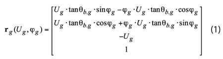
can be used. Here, in Eq. (1) is designated:
![]() and
and ![]() – curvilinear (Gaussian) coordinates of the bevel gear tooth flank G
– curvilinear (Gaussian) coordinates of the bevel gear tooth flank G
![]() – half of the base cone angle of the bevel gear
– half of the base cone angle of the bevel gear
When machining bevel gear teeth, the enveloping gear cutting head is rotating and traveling in lengthwise direction of the gear tooth. The rotation ![]() of the cutter about its axis of rotation and the translation of the cutter with a feed rate
of the cutter about its axis of rotation and the translation of the cutter with a feed rate ![]() are timed with each other. Within the roughing section, the rotation
are timed with each other. Within the roughing section, the rotation ![]() and the translation
and the translation ![]() are timed so that when the cutting tool turns through the angle
are timed so that when the cutting tool turns through the angle ![]() it travels at a distance
it travels at a distance ![]() . Here
. Here ![]() denotes the angle that spans over the roughing section of the cutting tool, and
denotes the angle that spans over the roughing section of the cutting tool, and ![]() denotes the distance between the two consequent positions
denotes the distance between the two consequent positions ![]() and
and ![]() of the axis of rotation of the enveloping gear cutting head.
of the axis of rotation of the enveloping gear cutting head.
Within the finishing section of the cutting tool the rotation ![]() and the translation
and the translation ![]() are timed in a manner that is similar to that just discussed. When the cutting tool turns through the angle
are timed in a manner that is similar to that just discussed. When the cutting tool turns through the angle ![]() it travels at a distance
it travels at a distance ![]() . Here
. Here ![]() denotes the angle that spans over the finishing section of the cutting tool, and
denotes the angle that spans over the finishing section of the cutting tool, and ![]() denotes the distance between the two consequent positions
denotes the distance between the two consequent positions ![]() and
and ![]() of the axis of rotation of the enveloping gear cutting head. The analytical representation of the bevel gear tooth flank to be machined, along with the just outlined kinematics of the enveloping gear cutting process, makes possible a derivation of the equation for the both portions of the generating surface of the gear cutting tool.
of the axis of rotation of the enveloping gear cutting head. The analytical representation of the bevel gear tooth flank to be machined, along with the just outlined kinematics of the enveloping gear cutting process, makes possible a derivation of the equation for the both portions of the generating surface of the gear cutting tool.
The blades of the enveloping gear cutter are relief ground when manufactured, and thus require sharpening on the rake face only. Blade-to-blade spacing, the angle of the plane of the front face, and the surface finish of the front face must all be closely controlled in sharpening. In addition, when new segments are assembled in heads the cleanliness of assembly, the accuracy of the position of segment-locating keys, and close control of segment-holding bolt tension are all necessities for proper cutting results.

Enveloping Round Cutter Head
The concept of enveloping cutting straight bevel gears can be extended to the area of production spur and helical gears. For this purpose the enveloping gear cutting head can be used (Figure 7). The work gear remains stationary when machining. The enveloping round gear cutting head is rotating ![]() about its axis of rotation that in Figure 7 is designated as
about its axis of rotation that in Figure 7 is designated as ![]() . All cutting teeth of the gear cutter are subdivided into several sections. Roughing teeth of the enveloping gear cutter remove most of the material from the tooth space of the work gear. The tooth height of the cutting teeth is incrementally increasing from the first roughing blade to the last cutting blade within the roughing section of the teeth of the cutter. Roughing teeth cut a chip of approximately rectangular cross-section that makes chip curling easy. No chip interference coming from adjacent cutting edges is observed on the roughing teeth. These allow for predicting high tool life of the enveloping gear cutter.
. All cutting teeth of the gear cutter are subdivided into several sections. Roughing teeth of the enveloping gear cutter remove most of the material from the tooth space of the work gear. The tooth height of the cutting teeth is incrementally increasing from the first roughing blade to the last cutting blade within the roughing section of the teeth of the cutter. Roughing teeth cut a chip of approximately rectangular cross-section that makes chip curling easy. No chip interference coming from adjacent cutting edges is observed on the roughing teeth. These allow for predicting high tool life of the enveloping gear cutter.
The roughing teeth are followed by the semi-finishing teeth, which remove a limited portion of the stock from the space-width of the gear blank. The main purpose of the semi-finishing teeth is to leave a uniformly distributed portion of stock for the finishing teeth. The tooth flanks of the work gear are generated by the finishing teeth. The accuracy of the finishing teeth directly affects the accuracy of the cut gears. For automatic loading and indexing the enveloping gear cutter is featuring the clearance between the last finishing cutting tooth and the first roughing cutting tooth. Profiling the finishing teeth of the enveloping gear cutter is identical to that for the internal round disk-type milling cutter. The cutting edges of the roughing and of the semi-finishing cutting teeth of the enveloping gear cutter are shifted inward the generating body of the gear-cutting tool.
Plane surfaces are convenient to be implemented as the rake surfaces of the enveloping round gear cutting head. The rake planes can be either through the axis of rotation of the enveloping gear cutting head (in this case the outer rake angle is zero,![]() ), or it can be offset at a certain distance from the axis
), or it can be offset at a certain distance from the axis ![]() (in this last case the outer rake angle is positive,(
(in this last case the outer rake angle is positive,(![]() ). Teeth clearance surfaces of the enveloping gear cutting head are relief ground for accuracy.
). Teeth clearance surfaces of the enveloping gear cutting head are relief ground for accuracy.
Reference
1) Radzevich, S.P., Gear Cutting Tools: Fundamentals of Design and Computation, CRC Press, Boca Raton, Florida, 2010, 786p.


