


At this time of year, as we are transitioning from the doldrums of winter through the rebirth of spring and the eventual sunshine of summer, there are certain childhood traditions that we all look forward to. In my youth, it was the opening day little league parade that reintroduced us to that glorious summertime treat, ice cream. Whether it was in a cup, in a dish, or on a cone, that simple treat was the perfect melding of sugar and cream.
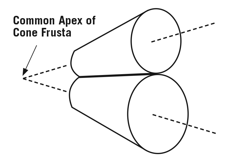
When dealing with gearing, the place where you will find cones are bevel gears. For these types of gears, the pitch surfaces are cones. The pitch diameters of mating bevel gears act as a frusta of cones as shown in Figures 1-2. These gears have taper elements because they are generated, and, in theory, operate on the surface of a sphere.
All bevel gears operate on intersecting axes and their design allows the redirection of motion. Since most bevel gear sets feature a different number of teeth on the driver pinion and the driven bevel gear, they also act as speed reduction mechanisms.
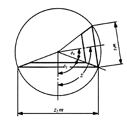
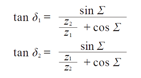
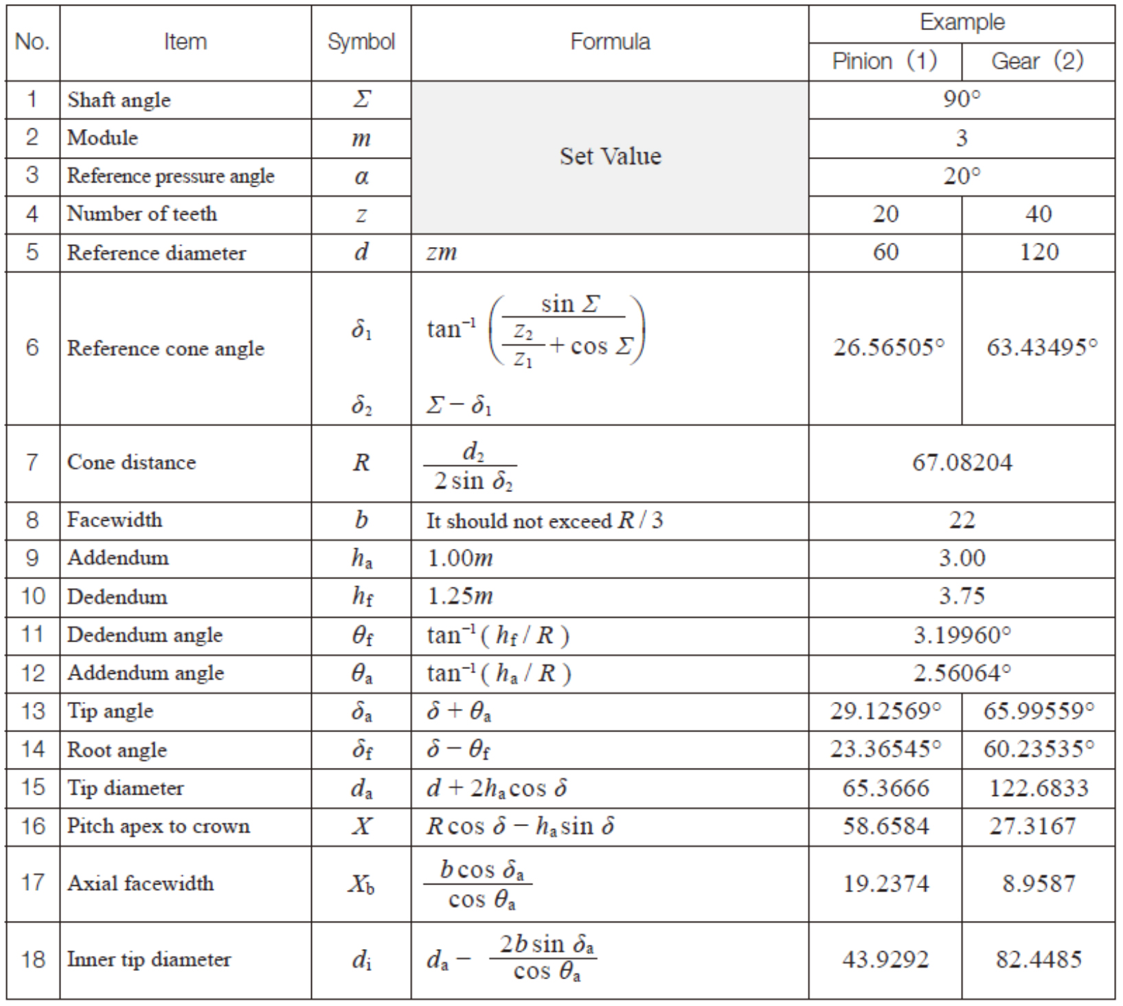
The relationship for all bevel gearing is as follows: Let z1 and z2 be pinion and gear numbers of teeth, Σ is the shaft angle, and reference cone angles are δ1 and δ2. To determine the values for each unknown, the following formulas are used:
There are various styles of bevel gears and they are described by the type of tooth form. Regardless of the style chosen, all bevel gears consist of two pitch cones that contact and roll with one another. The different types of the tooth forms include straight tooth, spiral tooth, coniflex, and Zerol.
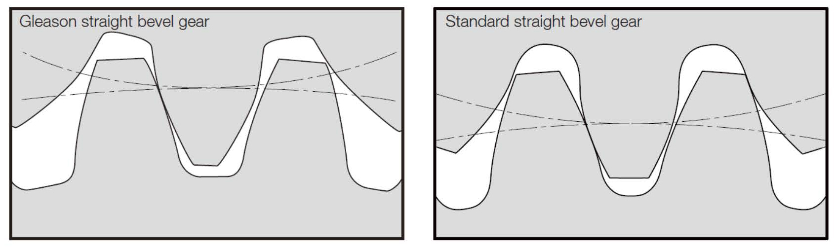
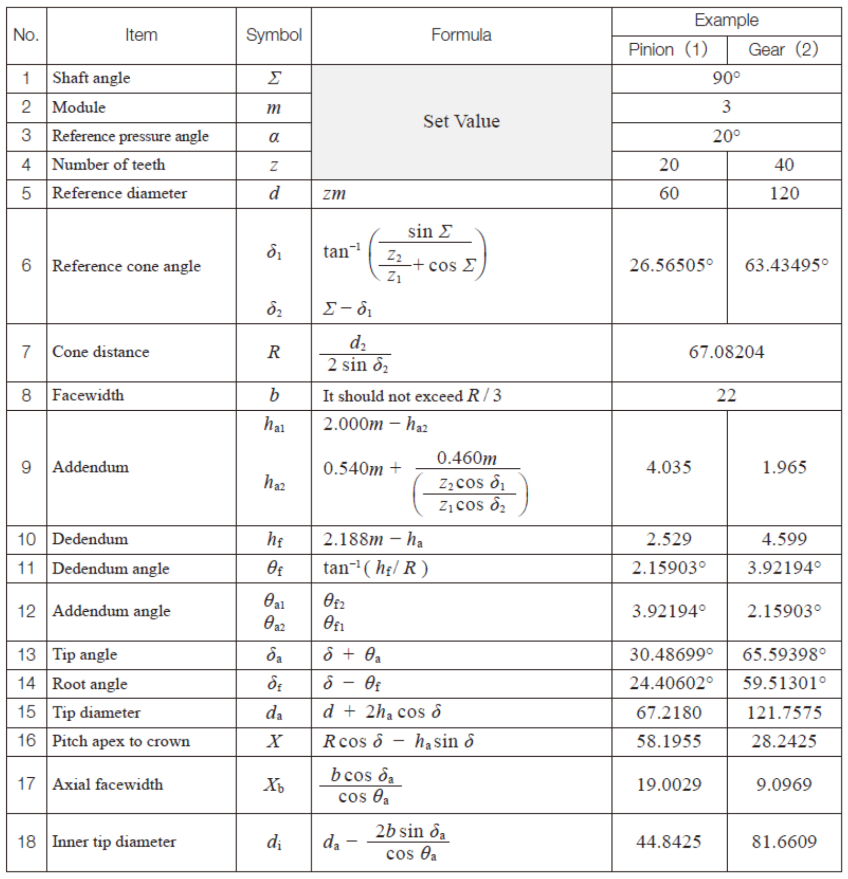
The most common style of bevel gear is the straight tooth bevel gear. This gear has teeth that are a tapered conical form and lay in the same direction as the pitch cone base line. The standard bevel gear tooth form is identical for both the bevel pinion and the bevel gear. This becomes a limiting factor for large speed ratios as the pinion is inherently weaker than the gear. The Gleason Coniflex bevel gear tooth form considers the speed ratio of the bevel gear set to determine the tooth shape of both the pinion gear and the bevel gear and enlarges the pinion tooth in higher ratio sets. Even with this additional compensation for tooth loading, bevel gear sets are typically limited to speed ratios of six to one (Figure 3).
An example calculation for standard straight tooth bevel gears appears in Table 1, and the same gear set generated in the Gleason Coniflex system is described in Table 2.
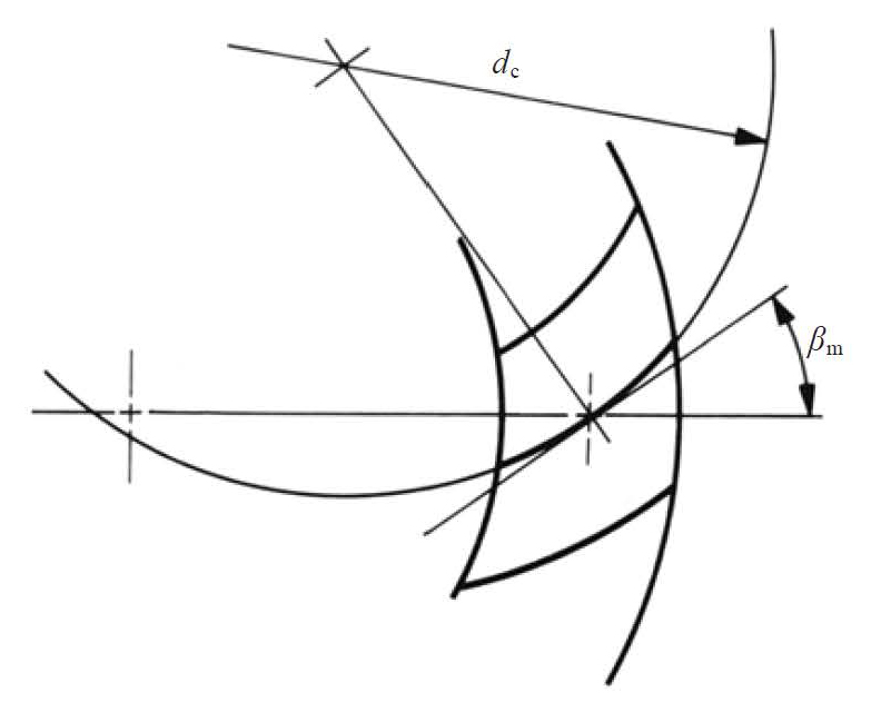
The second most common bevel gear style is the spiral bevel gear. The tooth of the spiral bevel gear is similar to that of a helical gear in that the tooth is produced at an angle to the bore axis. A spiral bevel gear is one with a spiral tooth flank as shown in Figure 4. The spiral is generally consistent with the curve of a cutter with the diameter dc. The spiral angle β is the angle between a generatrix element of the pitch cone and the tooth flank. The spiral angle just at the tooth flank center is called the mean spiral angle βm. The most common spiral angle for bevel gearing is 35 degrees. Spiral bevel gears are produced such that if the pinion has a left-hand spiral, the mating bevel gear must have a right-hand spiral of equal angle. Due to the spiral angle, spiral bevel gears produce axial thrust loads that need to be accounted for during operation.
The third tooth style for bevel gear sets is the Zerol bevel gear. This style of bevel gear is a hybrid that lies between the straight tooth form and the spiral tooth form. Unlike the spiral bevel gear in which the tooth is generated at an angle to the axis, the Zerol gear tooth is generated at an angle of zero degrees, but unlike the straight tooth bevel gear where the tooth is a taper conical form, the Zerol gear tooth is curved. This results in a spiral bevel style gear which mimics the loading pattern of a straight tooth bevel gear.
A common adjunct to the bevel gear family is the hypoid gear set. This specialty case of nonparallel-nonintersecting axes gearing looks similar to a spiral bevel gear set; however, the pinion sits offset to the intersecting axis, and its tooth form resembles a tapered thread. The speed ratio of a hypoid set is determined by the number of thread starts on the pinion relative to the number of teeth on the mating gear. As such, a hypoid configuration can result in very high-speed ratios in a very compact space.

As detailed in the examples above, there are many distinct styles of bevel gearing. Each operates as a rolling cone. However, my favorite cone can be found coming out of the window of the truck in Figure 5.
About the author Brian Dengel is general manager of KHK-USA, which is based in Mineola, New York. Go online to www.khkgears.us


