


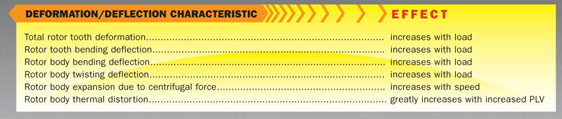
Every gear is subject to torque, resulting in elastic deformation of the toothed parts as well as the entire rotor body. Individual teeth bend, the pinion and wheel bodies twist, bend, and expand under the effect of the torque, load, and centrifugal forces. Special consideration must be taken to compensate for the forces on gear teeth and rotor bodies which cause deformation.
Additionally, churning and frictional losses in the bearings heat up the gear drive components, causing thermal expansion. The mean pinion temperature usually settles higher than that of the wheel (bull gear) due to less surface area for the heat to dissipate, and each pinion gear tooth goes through the mesh more than that of the bull gear teeth. With these effects, plus the resulting pumping action of the oil entering the gear mesh (based on the angle of the gear helix), the result is nonlinear temperature variations across the gear’s tooth flank face width. The temperature distribution is also influenced by the type of tooth lubrication (cooling) utilized. For this reason the theoretical tooth form must be modified to take into account these thermal distortions.
The objective of these resulting modifications — known as gear tooth form profile and longitudinal modifications — is to allow the gear teeth to move into and out of mesh with as little impact as possible in order to achieve a smooth and uniform transition of load and to minimize gear noise. Figure 1 shows an example of the deformation of a single helical tooth flank and the resulting required modification.

There are several influences to be considered in high-speed gears when optimizing load distribution along an entire gear tooth flank. They are:
In Figure 2 the oil enters the mesh from the left and travels along the tooth flank to the right. The thermal distortion is proportional to the referenced tooth temperatures.

Gear Ratings and Design
The influence of gear face width in the pitting resistance power rating assumes the entire active face width can be depended upon equally to support the entire load. The bending strength rating assumes the same with respect to face width. However, keeping the gear teeth in the theoretical position upon which a rotor set is rated is not an easy task to accomplish. All of the items listed above need to be considered independently in order to modify the rotor teeth in such a way as to compensate for all of the influences which cause less than perfect load distribution across the teeth.
Older technology was adapted to the advantages of double helical gears. These gears were usually constructed of softer through-hardened material with the pinion usually somewhat harder than the gear. This results in the pinion “working in” the gear during operation by wearing it in. This process wears down the unevenly loaded surface across the gear face width resulting from the mismatch created by the mechanical deformations until even load sharing across the gear face width is achieved. Since the load can be quite uneven, oftentimes highly loaded localized areas of the toothing begin to show some initial pitting. Due to the localized thermal deformation created by the higher sliding velocities of high-speed gears, this pitting could become quite severe. However, as the pinion and gear wear in, this condition slowly heals itself and the gearset develops a high degree of polish. Early day manufactured double helical turbo-gears ran at lower speeds than what is demanded of today’s highly loaded designs, and so this condition was not serious. Also, because of slower speed conditions, the shuttling of the pinion due to apex runout was not a serious concern and this, too, worked itself out under load as the gearset wore in. Figure 3 shows the influences of bending and torsion in a double helical gear.

Geometric increases in rotor size have a highly negative influence on high-speed gears because of increased PLV and rotor dynamics. With ever-increasing power and speeds it is necessary to find a solution to increase gear-rating capacity without increasing rotor geometry. This has been accomplished through the use of case-hardened gearing by carburizing and nitriding. Gears hardened in this way have a higher capacity due to strengthening of the gear root and a higher resistance to the surface Hertzian stress. This approach to design construction has benefited the use of double helical as well as single helical gears (Figure 4). The reader should keep in mind, however, that carburized gears must be accurate since they are neither expected nor capable of pitting well. They cannot wear themselves in. This is accomplished through the very accurate finishing method of gear grinding. Moreover, these grinders are also capable of accurately measuring the finished work piece. This improved accuracy is increasingly important because higher capacity demanded out of smaller elements increase mechanical deformations. Also, higher power requirements at higher speeds result in higher sliding velocities in the mesh, generating higher heat loads and thereby producing greater thermal distortion.

Although rating methods for gear teeth are based on rigid bodies in contact along the developed involute, in reality — and as previously stated — gear teeth deform under the influence of tooth bending and shear stresses, and so the teeth are flattened at the point of contact. Furthermore, every gear contains some degree of manufacturing error, which also alters the load variation. Since gear teeth are relatively stiff, small errors can have a significant effect. This can be exemplified by the sudden loading that takes place at the initial point of contact. In order to soften this impact as the rotors move in and out of mesh, the teeth flanks at both tip and root are relieved as seen in Figure 5. Thus, abruptness of load changes is reduced.

The necessary magnitudes (degrees) of modification are relatively small. They normally amount to a few hundredths of a millimeter. But even these small modifications greatly improve the tooth load bearing pattern and the safety of power transmission.
This forces the conclusion that the manufacturing accuracy of tooth-modified gears must be high. For the advantages of the flank modifications to take full effect, it is very important to measure exactly the finished, machined gears. Alongside pitch measurement (single pitch deviation and cumulative pitch deviations) the profile and helix contours must be recorded. In determining the form and degree of the modifications, the various factors of influence are investigated separately; the resulting modifications accumulate to give the total modification.
Modifying leads is very exacting, but experience dictates a solution. Each supplier is responsible for demonstrating the design approach. A new method describing modified leads due to mechanical deformation can be found in AGMA 927-A01.
Scuffing
Another design consideration — in addition to bending and pitting with high capacity high-speed gears — is a surface distress phenomenon referred to as scuffing. When gears are subject to highly loaded conditions and higher sliding velocities, the lubricant film may not adequately separate the surfaces. This results in localized damage or the tooth surface, or scuffing. As the gear teeth engage and disengage, a welding and tearing of the tooth surface from one tooth flank to another occurs. It appears as a dull matte finish at the extreme end regions of the contact path or near the points of a single pair of teeth in contact, resulting in adhesive wear.
Scuffing is not a fatigue phenomenon and may occur instantly, many times during the early stages of operation. Reasons for such an occurrence may be that scuffing resistance may not have been achieved inherently in the geometry of the gearset design, the lubricant in use was not in accordance with the original lubricant intended for the application, the surface roughness of the gearset was excessive, or proper tooth contact at startup was not achieved. Proper and careful adjustment to any one or a combination of these criteria can reduce scuffing risk.
Increasing the lubricant’s viscosity or reducing the supply temperature will have a positive influence on scuffing risk. Lubricants have a varied resistance to scuffing, dependent on their inherent quality. This is determined by a gear scuffing test measured by a test load rating in a four-square locked torque gear test stand. This rating is known as an “FZG level.” The higher the FZG number, the more resistant the lubricant is to scuffing.
A tempting solution to reduce the sliding velocities in the mesh is to reduce the pitch line and sliding velocities by reducing the gear center distance and make up the rating by increasing face width. However, except for special cases, and in spite of modified leads, L/Ds greater than those recommended by API 613-5 are not good design practice. Long face widths increase toothing distortion with increased thermal losses due to oil quenching as it is pumped across the face width in the gear mesh, and mechanical deformation requires a deeper correction to the lead as well. Therefore, the lead modification becomes more sensitive to good control of even load distribution over the entire face width.
The criteria with which to determine how much sliding velocity is allowed is directly related to the local temperature occurring in the contact area of the gear teeth. This temperature is known as the “flash temperature,” and it can be calculated for any local point on the involute along the path of contact. The maximum flash temperature calculated becomes a criterion by which a gearset is rated for its maximum power transmission capability. Therefore, a permissible flash temperature is an additional criterion for determining the power rating of a particular gearset. This additional criterion is treated with equal importance as the contact power and the bending strength power ratings.
Analysis of scuffing is difficult, and there are few methods available. Industry does not have a single-minded perspective as to its analysis, but acknowledges its existence. Experience is a key consideration in high-capacity gears. Suppliers should demonstrate a selected method of analysis. AGMA 925-A03 provides alternative methods of analysis, which present the problem in detail. Further, Annex B in ANSI/AGMA 6011-I03 also has a proposed verification check for scuffing risk. It is simple to apply, and not complicated to understand. It is not a design solution, but rather a design check against a go/no-go criteria.


