


The single-pass bore finishing process was originally developed to improve the bore quality of cast iron components, such as hydraulic valve bodies. For many years it was thought that while ideally suited for similar through-bore applications, its use would be limited. This initial belief has proven to be unfounded, as the single-pass process now has been developed to a point where almost any application in almost any type of material is possible. For example, as well as the many cast iron applications that are successfully being finished with this process, today there is probably an equal amount being done in other materials. These materials include varieties of hard and soft steel, aluminum, bronze, brass, ceramics and chrome, as well as multi-material assemblies. The single-pass process is also now capable of finishing most blind bores, as well as through.
This paper will explain the basic principles of the single-pass process, and provide details on some of the latest advancements that have been made.
Process
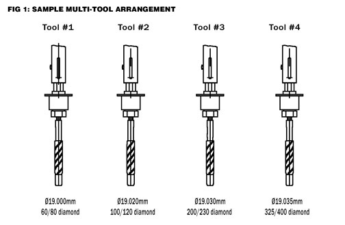
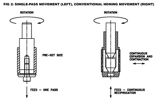
The single-pass bore finishing process involves a series of pre-set diamond coated tools that get passed through a bore with a single in-and-out stroke movement while the tool, part, or both are rotating. The number of tools that are used will vary depending upon the amount of stock to be removed, surface finish requirement, geometrical requirements, and material make up. Generally each tool is set progressively larger in diameter, in ever reducing increments, while the size of the diamond particles is also reduced. This arrangement allows tools with larger diamond particles that remove relatively large amounts of material, and tools with smaller diamond particles that have finer surface finish capabilities, to be used progressively for maximum efficiency. (Figure 1) (Figure 2)
Benefits/Capabilities
The single-pass process can be tailored to meet the requirements of various applications and, as such, obtain different results. For example, some applications may require very critical bore geometry and allow longer cycle times, while others may have less critical geometry but require a higher throughput at the lowest possible cost per piece.
Higher bore precision: The key to the single-pass process is to allow the diamond tooling to follow the existing centerline of the bore to be finished with as little pressure as possible. This is normally done by allowing the tool, part, or both to float. Depending on many other variables, bore geometry to better than 0.2µm (.000008”) is possible. Since all of the diamond tools are set to specific sizes and do not require expansion during each cycle, the single-pass process is able to achieve unsurpassed size control in production (1µm with near perfect repeatability). These results are very predictable and repeatable, thus lend perfectly to Statistical Process Control.
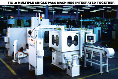
Lower cost: The diamond portion of the tooling wears very slowly in production, which allows for tool life to exceed 100,000 parts in many applications. With an average of four single-pass tools used in a setup, the perishable tool cost is usually under $0.01 per finished part. The long life of the tooling also contributes to very little downtime due to tool change. (Figure 3)
Systems Approach
In order to obtain the greatest potential with this process it is necessary for all of the systems components to be correctly designed for the application. These components include tool design and layout, part holding, tool holding, coolant/filtration, machine tool, and possible automation.
Tool Design: Besides determining the number of required tools and the diamond size of each, tool lengths, flute styles, adjustment features, and tapers also need to be considered.
Part Holding: Proper fixture design is vital to the success of the process. The part must be accurately located in a manner that will not transmit any distortion into the bore that is being finished. This distortion may come directly from the clamping forces, or generated during the cut by radial forces from the part itself pivoting around an intended anti-rotation device. In many cases the best geometrical precision can be obtained by using bearing-mounted floating fixtures. The design of the fixture should also take into consideration ease of loading/unloading and changeover capability.
Tool Holding: In applications where it is impractical to float the fixture, tool holders with some form of float movement are often utilized. These floating tool holders come in various sizes and designs and, as is the case with all of these components, it is necessary to use the one best suited for the particular application.
Coolant/Filtration: The relatively slow spindle speeds, combined with the free cutting diamond tooling, allow the single-pass process to operate without developing much heat. The important characteristic of the coolant that is used with this process is lubricity rather than cooling. This allows the swarf that is produced to be flushed away without embedding (loading) into the tool. Coolants such as honing oils or certain water based products (depending upon the application) are necessary. Cleanliness of the coolant can also have a major influence on the overall results; filtration to better than 10µm is advised for most applications.
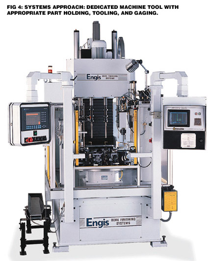
Machine Tool: In order to best utilize all of these special components that make up the ideal single-pass bore finishing system, dedicated machine tools have been developed. These machine tools often include CNC motion controlled columns, extended stroke capabilities, multiple spindle arrangements, and rotary tables with sufficient cutouts for tool clearance. They can also include additional features such as automation and automatic gaging (additional information on these features are detailed later in the paper).
(Figure 4)
Advancements
Manufacturers are continually pushing the envelope in regards to what can be accomplished with the single-pass process. Improved tool, fixture, and machine designs have allowed for increased production rates as well as improved bore precision. The following are some of the latest advancements that have been made.
Bore precision: With upgraded CNC motion capability, combined with advanced fixture design, the single-pass process can now achieve higher bore precision than ever before. Bore roundness and straightness to better than 0.2um (.000008”) is possible. In fact, total bore cyclindricity to better than 0.4um (.000016”) has been achieved.
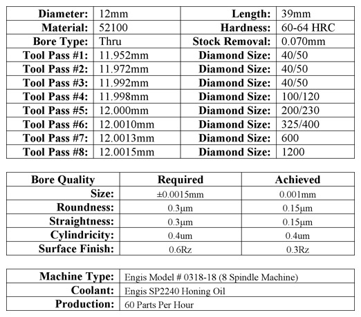
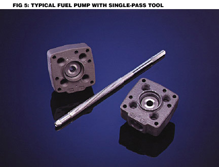
Case History #1: (Fuel Pump)
Blind bore: As illustrated in the following case histories, blind bores are now being successfully finished with the single-pass process. The term blind bore is used whenever one end of the bore has a clearance restriction that will not allow much of the finishing tool to pass through. In some cases, components have been successfully finished without any clearance at all. (Bore clearance is the distance from the lowest part of the bore to be finished to a restriction that does not allow the finishing tool to pass).
(Table 1)
(Figure 5)
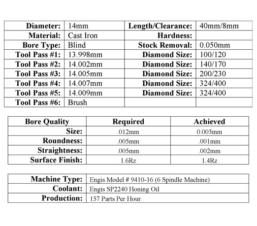
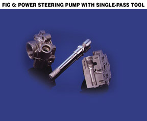
Case History #2: (Power Steering Pump)
Cost Reductions: The following case histories are good examples of where component manufacturers were able to improve bore quality and dramatically reduce costs by switching from conventional honing to the single-pass process.
(Table 2)
(Figure 6)
Case History #3: (Hydraulic Timing Component)
The bore geometry for this application was relatively open. However, with the blind bore condition—combined with distortion from heat treat—economically finishing this part in production with a conventional honing process proved to be difficult and expensive. As an alternative the manufacturer switched part of their production over to using the single-pass process. The system that was designed included six single-pass tools with floating holders, pneumatic part clamping with regulated pressure to minimize distortion, and automatic gaging with robotic automation. The single-pass process produced 480 parts per hour with very little downtime and reduced the perishable tool costs to less than $0.01 per part. Because of these benefits the entire production was eventually switched over to the single-pass process.
(Table 3)
(Figure 7)
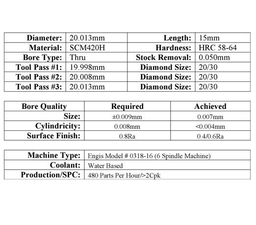
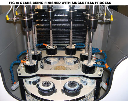
Case History #4: (Gears)
The bore finishing of transmission gears has traditionally been performed with ID grinding or conventional honing processes. More and more manufacturers are now switching over to the single-pass process for this operation and realizing costs savings of as much as 50 percent. In the following application perishable tool cost is less than $0.01 per part with the single-pass process, verses over $0.02 per part with conventional honing. Additional savings are also achieved by having a greater up-time due to less frequent tool changes.
Soft Material: Soft, gummy material such as aluminum and bronze can be successfully finished with the single-pass process. Normally an oil coolant would be recommended for these materials, but in some cases specific water-based coolants can be utilized.
(Table 4)
(Figure 8)
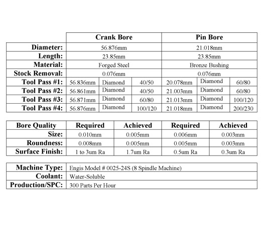
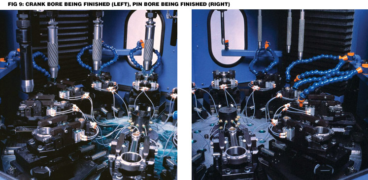
Case History #5: (Connecting Rod)
This case history is a typical example of high production bore finishing of automotive connecting rods. The soft bronze material in the pin bores is being successfully finished to better than 0.5Ra, and with a water-based coolant. For this process both crank and pin bores are finished simultaneously with four diamond single-pass tools apiece. The rods are held securely on a locating plate which is positioned on an X-Y (axis) floating fixture base. With this setup the radial alignment of the two bores (bend and twist), along with perpendicularity to the locating surface, can be improved. The life of the diamond tools that are used on the forged steel crank bores average approximately 80,000 parts, while the life of the diamond tools used on the bronze pin bores often exceed 1,000,000. The total perishable tooling cost for finishing both bores is roughly $0.03.
Cross Hatch Patterns: Another recent development that has been made in the single-pass style of bore finishing includes creating various “cross hatch,” or “sine curve” scratch patterns on the finished bores. The depth and angle of the scratch pattern can vary depending upon the size of the superabrasive grit, material to be finished, and operating speeds and feeds. These patterns are thought to be beneficial in the retaining of oil in engine cylinder bores. This pattern is achieved by feeding a proprietary designed single pass-style tool through a bore at a higher than normal feed rate—which only removes a portion of the parts material—then reciprocating the tool through the bore a number of times at a set spindle speed and feed rate. The spindle speed and feed rate will determine the crosshatch angle. With this method, many of the advantages of the single-pass method are obtained, as well as the desired cross hatch pattern.
Adding a controlled peck method to the process may also produce a similar pattern (sine curve). This method allows for the finishing of long uninterrupted bores in even the most gummy of materials by allowing the chip that is produced to be broken up and a fresh supply of lubricating fluid to enter the work area. This method is also advantageous in applications where it is important to keep the cutting stresses down to an absolute minimum, such as in the finishing of thin-walled components. The following case histories illustrate examples of applications where either the cross hatch, or sine curve patterns, are produced.
(Table 5)
(Figure 9)
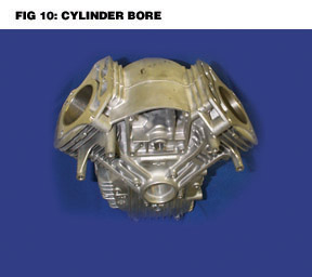
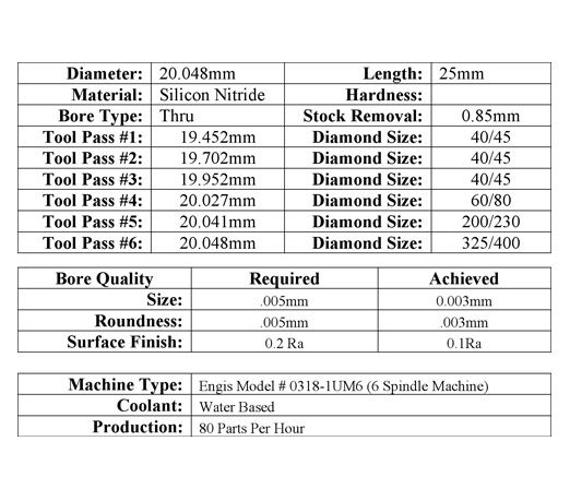
Case History #6: (Cylinder Bore)
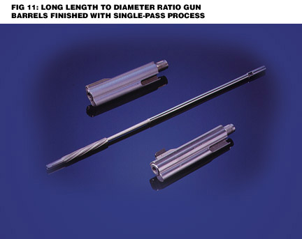
Long Length to Bore Ratio: One of the myths that have been associated with the single-pass process is that it is only well suited for finishing relatively short bores. As illustrated in some of the case histories in this paper, bores with length to diameter ratios of over 10 to 1 do not present a problem. With the proper tooling, fixture, and machine tool, the single-pass process is even capable of removing a camber or “banana” condition from the bore in many applications.
(Table 6)
(Figure 10)
Case History #7: (Fuel Pump)
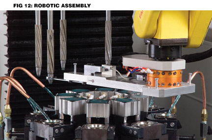
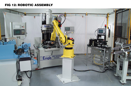
Automation and Automatic Tool Adjustment: Various automation, auto-gaging, and auto-tool size compensation systems have been developed for the single-pass process, with each designed to further reduce labor costs. Case history #8 illustrates one particular application in which the component manufacturer wanted to have each finishing cell completely automated so that one operator could oversee a couple of cells at a time. Included in each cell are one single-pass bore finishing system; one OD grinding machine; one OD crowning machine; one automatic gage; and one robotic automation package. The automatic gage is set up to inspect bore size, OD size, face run-out to the bore, and OD to bore concentricity. Information from these measurements is used to automatically adjust the grinding and bore finishing sizes when necessary. To automatically adjust the single-pass bore finishing tooling, the robot first automatically changes its end of arm tooling and then proceeds to turn the front adjusting nut on each individual tool as needed. The robot then changes the end of arm tooling back to the grippers, loads a new part, and continues on with the automatic cycle.
Other forms of automatically adjusting the single-pass tooling include using a draw bar through each spindle to move the tapered mandrel in relationship to the sleeve.
(Figure 7)
(Figure 11)
Case History #8: (Diesel Roller)
(Table 8)
(Figure 12)
(Figure 12b)
Summary
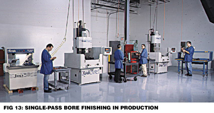
The single-pass process has emerged as the preferred method of finishing close tolerance bores in production. The driving factor for this has been the ability to achieve unsurpassed precision at the lowest cost per piece. With advancements such as blind-bore finishing, automatic size compensation, CNC motion capability, extended bore-length finishing, cross-hatch capability, soft material finishing and bow correction capability, more users than ever are now able to obtain the benefits associated with the single-pass process. (Figure 13)


