


The parameters that usually have to be examined are bearing deflections, shaft deflections, pinion torsional windup, housing deflections, and external forces on the input and output shafts. In this column we're only going to address the first three.
We will use the same example as last month. Our example is the third reduction mesh of a large industrial gearbox. It is a 15/57 tooth, 13 module, carburized and ground gear set with a 206mm face width and manufactured to Grade A5 accuracy per AGMA 2015-1-A01. Center distance is 482mm, and both the pinion and gear shafts are supported on spherical roller bearings. The first parameter is bearing deflection.
• Bearing Deflection: When torque is applied to the shafts that support the pinion and gear, the tangential and separating forces at the gear mesh are transmitted through the shafts and bearings to the housing. The forces cause the bearing races and rolling elements to compress, and the shafts move slightly in a radial direction. The amount the shafts move for a given load can be obtained from the bearing manufacturer. The direction of the movement, and how this affects tooth alignment along the line of action of the mesh, will be the same as for the bearing radial internal clearance that we discussed last month. In our example, calculations determine that the misalignment across the face width is 3µm due to pinion shaft bearing deflections and 2µm due to gear shaft bearing deflections.
• Pinion Torsional Windup: When torque is applied to shafts they twist, and small diameter shafts twist more than large shafts. Since gearbox designers like to get as much ratio as they can in a gear set, they tend to use small pinion diameters. Unfortunately, this can sometimes lead to excessive twisting of the shaft and too much operating misalignment. A rule of thumb used to avoid excessive torsional windup is to keep the gear mesh face width divided by the pinion operating pitch diameter, or F/d ratio to less than 1.0. In our example the F/d ratio is 1.03, and at the operating load the calculated misalignment due to pinion torsional windup is 28µm across the face width.
• Shaft Bending Deflection: The gear mesh loads also put forces on the pinion and gear shafts that cause the shafts to bend. This bending can result in a slope in the shaft where the pinions and gears are mounted, which translates into tooth misalignment at the mesh. The amount and direction of the shaft deflections, and how they affect the tooth alignment along the line of action, needs to be calculated. In our example, calculations determine that the misalignment across the face width is 12µm due to pinion shaft bending, and 9µm due to gear shaft bending.
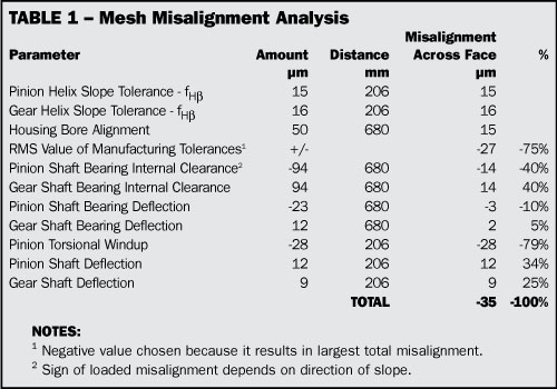
Table 1 from last month has been expanded to include the items discussed above and shows the direction and contribution of each to the total. This allows you to see which parameter has the largest affect and what parameter needs to be improved if the overall misalignment is too large. Since the manufacturing tolerances are random, and are rarely all a maximum in the worst direction, some method of combining them is usually used. One method is to calculate the root mean square value of the worst-case manufacturing tolerances translated into the plane of action. The resulting +/- misalignment value is then added to the misalignment due to clearance and deflection. In our example the RMS value of the helix and bore alignment tolerances is +/- 27µm. When this value is added to the bearing clearance and deflection values, the predicted worst-case operating misalignment is 35µm.
This value of predicted misalignment is then used to calculate the tooth contact and bending stresses across the face width of the mesh. If the stress distribution across the face is not uniform enough, changes have to be made. This can be done by reducing manufacturing tolerances and/or deflections, or by using helix modifications to compensate for the deflections under load.


