


Never assume gripping a gear is easy. Gear workholding is possibly the most complex workholding challenge we face because of the complexities of the gear forms themselves coupled with the frequent need for tight tolerances. Done right, however, it can enhance the accuracy of the manufacturing process and thus the quality of the finished workpiece. In some instances, benefits of proper workholding can also reduce setup times and speed changeover, further strengthening a firm’s competitive position.
Gears come in many configurations, but some of the most common are spur (or ring) gears, helical gears, and bevel gears. These style gears can be found in automotive, aerospace, and small motor industries, with much larger gears being manufactured for the wind power market.
You may well recall that a bevel gear is shaped like a right circular cone with most of its tip removed. When two bevel gears mesh, their imaginary vertices must occupy the same point. Their shaft axes also intersect at this point, forming an arbitrary non-straight angle between the shafts that can be anything except zero or 180 degrees.
A spur gear is a ring with teeth that is fitted on the periphery of a flexplate or flywheel of an internal combustion engine. Its teeth are driven by the smaller gear (the pinion) of the engine’s starter motor. Its primary function is to transfer torque from the starter motor pinion to the flywheel or flexplate to rotate the engine and begin the cycle.
With helical gears, the leading edges of the teeth are not parallel to the axis of rotation, but are set at an angle. Since the gear is curved, this angling causes the tooth shape to be a segment of a helix. These gears can be meshed in parallel or crossed orientations. The former refers to when the shafts are parallel to each other; this is the most common orientation.
As we survey this broad range of gear machining applications, excluding hobbing, we see that the following workholding devices are most commonly used:

Jaw Chuck (Figure 1): With this type of chuck, the jaws move in and out when actuated by a draw tube or draw bar utilizing a wedge or levers. This chuck is used in the most basic form of spur or helical gear machining, which is for holding the gear O.D. while machining is performed on the face and/or I.D. of the gear.

Diaphragm Chuck (Figure 2): This uses the deformation of a flexible material to grip a workpiece and is commonly operated by a clamping cylinder. This is the most common form of chuck used in machining spur or helical gears.

Collet Chuck (Figure 3): This is a workholding device that uses a spline collet. The spline can be used to grip either on the I.D. or the O.D. of the gear, and is machined to match the gear form.

Pull-Back Chuck (Figure 4): This type of chuck grips the workpiece while simultaneously pulling in the axial direction against a fixed locator. It is used for machining bevel gears as it will pull down on the fixture that is holding the gear to keep it in place while being machined. A pin plate or gear nest is usually required for locating the gear. Helical and spur gears in the unhardened state can also be chucked with pull-back chucks.
Deciding which workholding device to choose will depend on the application. Relevant variables include the nature of the machining process and the quality requirements. The primary variable, though, is the type of gear to be processed.
The Bevel Gear
Of the three gear types mentioned above, bevel gears present the greatest workholding challenge because the gear form is sloped on an angle. One way to deal with this challenge is to create a pin plate. The plate, which lies flat, has multiple holes for holding ball-topped pins. The bevel gear will be placed upon those pins, and the ball of those pins will have been sized so that when that bevel gear is positioned, the balls are tangent to the pitch diameter of the tooth form on the bevel gear.
The pitch diameter is a position on the gear that is located between the top of the gear tooth (the outside diameter or major diameter, also referred to as the top land), and the bottom of the tooth (the minor diameter and bottom land). It marks the spot at which the incoming mating tooth contacts the gear. Its value is based on the number of teeth, the normal module (or normal diametral pitch), and the helix angle, and there is a standard equation for calculating it:
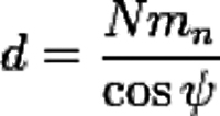 in metric units or
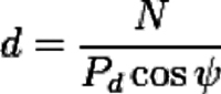 in imperial units.
Where higher accuracies are called for, as in the case of a Geometric Dimensioning & Tolerancing (GD&T) requirement to run true to the pitch, pins (ITW-112F) can be used to locate on that pitch diameter.
Bear in mind that the pins are used to locate, not to hold the gear. The actual holding can be performed by a variety of different chucks or finger clamps. The pin plate is an economical solution and a flexible one. That’s because the plate can have multiple holes permitting multiple pin configurations, allowing it to accommodate a variety of bevel gear geometries, all held by the same chuck.
Another workholding solution for bevel gears employs a gear nest (Figure 5). This is both more expensive and more accurate. The gear nest, which has teeth that mimic the bevel gear’s angled tooth form, mounts in the top of the chuck. The gear rests in it and the gear nest’s teeth locate on the pitch of the gear tooth form. Again, the chuck is used simply to hold, but not to locate the gear, and so a variety of chucks can be employed. However, many manufacturers favor pull-back style chucks for bevel gear machining operations where a pin plate or gear nest is used because the pulling action can provide added support and stability in holding the gear securely to the pin plate and gear nest fixtures. The gear nest is not as flexible as the pin plate, in that the gear nest is dedicated to one gear, while a pin plate can be configured for multiple gears.

The Spur Gear and its Cousins
When discussing workholding for spur gears we are in fact discussing most gear workholding situations commonly encountered in industry today. That’s because 1) the spur gear is so widely employed, and 2) because what applies to spur gears is generally applicable to the broad range of other commonly used, circular-shaped gears, excluding of course bevel gears, as as well as various gears with highly specialized uses. With spur gears, as with helical and most other gears, you are typically gripping the outside, or major, diameter. In the case of an I.D. type gear form you might have to resort to some special designs, like a collet chuck with a spline form on its outside diameter, to grip the I.D. That, however, is out of the norm, and typically you are gripping on the outside diameter of the gear.
The most basic way to grip this O.D. is with a sliding jaw chuck with standard jaws—a simple chuck for a simple process. However, if you have to machine a diameter that runs true to a pitch diameter, you will need to look beyond the sliding jaw chuck.
The most typical solution in these cases where added accuracy is required is to use gear pins that are housed in the chuck. Unlike bevel gear manufacturing where ball top pins are used, spur gears will generally use cone point pins or wedge-shaped pins. Both are highly engineered items. Typically three will be used, but depending on the size of the gear as many as six may be employed to enable the chuck to grip on the pitch diameter. Once the chuck locates and grips on the pitch diameter, subsequent machining will be true to that pitch.
Typically in a bevel gear application grip force isn’t that important, but in a ring gear application where the chuck is actually centering the part, grip force can play a crucial role. Of course, as with all workholding, too high a grip force can distort the part, while applying too little force can permit the part to move during processing. Based on the part specifications or the machining process, a variety of chucks can be used in spur gear or a helical ring gear machining, including collet chucks, where in some cases the gear tooth form is machined into the gripping diameter of the chuck. Other common choices include pull-back chucks and sliding jaw chucks, with sliding jaw chucks seeming to predominate in applications where high accuracies are not required. In cases where high accuracies and especially tight tolerances are called for, however, the industry standard is the diaphragm chuck. It is estimated that up to 75% of the ring and helical gear applications where gear pins are used employ diaphragm chucks.
In addition to its high accuracy, which is the main selling point of the diaphragm chuck, it has other advantages as well. Because it employs the outward pressure from a flexible material to grip the part, it has relatively few moving parts, reducing maintenance requirements. Also, they can be sealed to withstand harsh work environments, including grinding sludge and coolant.
Part Loading
Whether the gears are manually loaded or automatically loaded by a robot or other device is also an important workholding consideration. Traditionally, when parts were loaded by hand, the amount of load clearance was small. With robots this has had to be increased. So, in order to ensure accurate positioning without the need for human intervention manufacturers often rely on positioning aids or guides.
In gear manufacturing these can take the form of synchronizing, or synchro, pins, so called because they synchronize the gear with the chuck, allowing accurate loading and a secure seat within the chuck. This simple and economical solution can increase the accuracy and productivity of automated gear production.
Timing and Costs
For those who buy and use workholding devices, two obvious—and vital—questions are: How much will it cost and how soon can I get it? The answers vary widely, again depending on the needs of the process. The simpler chucks, used to grip the OD in non-demanding applications, can be supplied off the shelf. If, however, you need to grip the gear tooth form, lead time will be longer because more than likely the chuck will have to be custom designed and built to meet your specifications. Lead time in these cases will generally range anywhere from 12 to 20 weeks, based on the variety of gears to be held and their size. Costs vary even more. The most basic chuck, supplied off the shelf, might be $3,000. A custom designed and built chuck, on the other hand, could range in cost anywhere from $10,000 up to $100,000, and in lead time from a month to—for the most demanding applications—up to six months.
Chuck Manufacturing is a Key Variable
In terms of chuck manufacturing, perhaps the most critical factor is having the grip diameter on a common centerline. For instance, when a diaphragm is ground, the grip diameter can be ground to a common centerline, based on single point of the grinding wheel to the grip diameter, ensuring optimum accuracy. The grinding wheel stays in one position while the diaphragm rotates on a common centerline. This latter process opens the door to several sources of potential inaccuracy. Other designs may utilize a grip diameter whose accuracy is determined on independent bores or jaws. Consider a sliding jaw chuck as an example. While the base jaws are tied to a common actuator, there are inaccuracies inherent to the design and manufacture of this style chuck. Those inaccuracies make a sliding jaw chuck incapable of matching the accuracies of a diaphragm chuck. The base jaws are manufactured independently. The three slide ways (the area of the chuck body that the jaws fit into), have to be manufactured “point to point”. That is, the body has to be rotated and the tooling, such as milling cutters or grinding wheels, have to be positioned to machine the ways of the body. This build-up of error could seriously impact the quality of the finished product.
An often-overlooked aspect of chuck quality is the material used in the manufacturing process. Take diaphragm chucks, for example; many are made of bar stock, while some are built from forged material. There are subtle but real advantages to using a forged material in this instance, chiefly in terms of the accuracy and consistency of the grip diameter. Durability is another aspect —some diaphragm chucks made of forged material have been in use for 20+ years.
Working With a Workholding Supplier
In all cases except when buying the most basic chuck for non-demanding applications, it is essential to supply your workholding supplier with adequate data on the gears you plan to produce. This includes pitch diameter, and the related dimension over a rolls, as well as the number of teeth, the hardness of the gear you are gripping, the machining process you plan to employ, and what type of tolerancing is on the blueprint. Additionally, the supplier should know if your need is for a single dedicated part or is it multiple parts which will require interchangeable tooling. This is the sort of information you should be prepared to present to your potential workholding supplier in order to secure accurate quotes, a smooth and efficient start to your working relationship if you proceed that far, and–ultimately–the optimum chuck for your application.
Bear in mind also that your workholding supplier’s engineering sales team is your chief point of contact in the process, and play a key role in securing the right workholding solution for your needs. As such, they need to be knowledgeable about the manufacturing process for the gear. They also have to understand the quality requirements, including whatever GD&T requirements are called for in the process. They need to be able to examine the blueprint to determine those specifications, and be fully briefed on the varieties of gears to be produced. A veteran salesman’s experience and expertise can prove vital in this initial stage; for instance, a gear will experience some distortion during machining, and an experienced salesman will understand what works well and what doesn’t with a thin-walled gear.
Conclusions
The two key factors in chuck selection are the type of gear to be produced and the accuracy needed. Where accuracy is not a paramount consideration, you might wish to go with a lower cost workholding solution. Where high accuracy and factors such as variations in the gears to be produced as well as the number of gears to be produced add complexity to the issue, the right solution will significantly impact part quality and, often, productivity, but it will rarely be the cheapest.


