


This is the third of a three-part series of instructions to assist engineering designers and detailers with the process of correctly laying out bevel and hypoid gear teeth. Each guide assumes that the basic gear tooth design information is already at hand (for hypoids these items would be the shaft angle, offset, hand of spiral, gear pitch diameter, pinion outside diameter, gear outer cone distance, face widths, gear pitch angle, pinion and gear face angles, pinion and gear root angles, the outer gear addendum and dedendum, the gear crown to crossing point, the pinion root apex beyond crossing point, the pinion face apex beyond crossing point, the pinion front crown to crossing point, and the pinion crown to crossing point). See the appendix at the end of this article if you want to know more about these items. This basic information is usually available in the form of a gear “dimension sheet,” which may have been calculated by your own gear engineer. As a gear design and manufacturing company, Nissei provides gear dimension sheet information to customers as part of our service. Publications on the subject are also readily available from the AGMA (American Gear Manufacturers Association) or from The Gleason Works.
To create a dimension sheet, certain information is usually required. This information includes the applied loads, speed, shaft angle, amount and direction of offset, gear materials, heat treatment, lubrication method, operating temperature, required life, and operating conditions affecting the driving and driven loads. An initial size with pitch, offset, face width, tooth pressure angle, spiral angle, and hand of spiral is chosen and the bending stresses and contact stresses for the resulting design are calculated. An estimated life can then be determined and compared to the requirement. This can be an iterative procedure involving several sizing trials before a dimension sheet is finalized. Taking the data listed on a gear dimension sheet and converting it into a drawing is the next key step. It is the connecting step between the gear tooth design and the creation of the rest of the structure–the gear blank with its bearing arrangement and input or output features and then, ultimately, the housing itself.
Hypoid gears are similar in appearance to spiral bevel gears, with the major distinction being that the pinion axis is offset in a direction above or below the centerline of the gear member. The direction of offset is chosen (relative to the hand of spiral) so that the pinion diameter increases, which is a natural result of the geometry involved. This enlargement factor allows higher numerical reduction ratios to be practical by ensuring the pinion teeth and pinion shaft are sufficiently large in diameter to carry the applied torque. Another benefit of the enlargement is that more teeth are brought into contact at any given position of rotation. This increased “contact ratio” improves the tooth load sharing for greater load-carrying ability and smoother, quieter rolling. The enlargement of the pinion is also directly responsible for the relative sliding motion that must take place with hypoids and that contributes, in large part, to the efficiency of the design. The number of pinion and gear teeth determines the ratio. With spiral bevel gears, the circumferences at any section along the pitch cones the teeth are arrayed on is in exactly the same ratio as the teeth. In theory the cones roll together without slipping in perfect timing without leading or lagging the tooth action. At the pitch line a pure rolling motion takes place. In the case of a hypoid, because the pinion teeth are arrayed on a surface of revolution that is larger in circumference than that dictated by the ratio of the teeth, the teeth are subject to a compensatory slipping motion (lengthwise sliding) superimposed on their rotation. The lengthwise sliding is beneficial in the case of parts that are to be lapped after heat treating.
There is a note of caution here related to the direction of offset and the choice of hand of spiral of the hypoid. The designer will need to determine the direction of the offset required by the application, which is defined as either “above center” or “below center” (refer to the appendix at the end of this article for more information). A below center choice will dictate a right hand gear running with a left hand pinion. An above center design dictates a left hand gear and a right hand pinion. If the incorrect hand of spiral is specified when ordering a hypoid gear set, it will be impossible to assemble the parts in the housing.
Conventional hypoids run in ratio from 1:1 (uncommon) to 10:1. Hypoids above 10:1 ratio have traditionally been referred to as high ratio hypoids or, more recently, as super ratio hypoids. The acronyms HRH and SRH–Gleason trade names–are commonly used. HRH ratios as high as 360:1 have been manufactured, with ratios to 120:1 being most common. There are two kinds of HRHs, referred to as the tapered-type and the crown-type.
The tapered-type HRH takes its name from the outward conical appearance of the pinion and gear. The conical shape of the pinion allows the largest diameter shaft to be used to support the pinion, which is generally an overhung mounting design (no bearing support at the toe end of the pinion).
The crown-type HRH takes its name from the gear member, which looks like a “crown gear”: the face angle is at 90 degrees to the axis. The mating pinion has a nearly cylindrical shape (discussed in the following paragraphs), a geometry which is more well suited for applications where a straddle-mounted pinion bearing arrangement is desirable. The vast majority of bevel and hypoid gears are designed for a shaft angle of 90 degrees, which we will use for our examples.
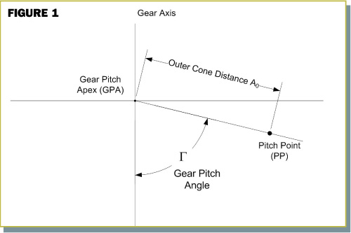
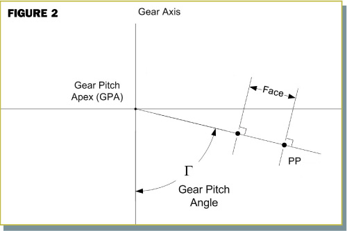
The hypoid construction starts by drawing the gear member in cross-sectional view. Strike a vertical line for the gear axis, select a point on the axis for the gear pitch apex, and from this point extend a line at the gear pitch angle. Measure along this line an amount equal to the outer cone distance and mark a point. This establishes the pitch point on the pitch line (see figure 1). Construct a normal through the pitch point and another normal a distance away on the pitch line equal to the face width. These normals identify the outer and inner ends respectively of the gear teeth (figure 2).
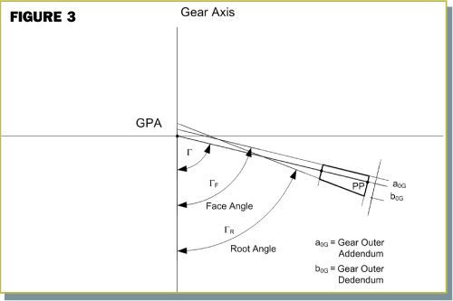
Along the outer normal, mark off the gear outer addendum and the gear outer dedendum. Draw a line from the gear outer addendum point at the face angle value to connect with the inner normal. Draw a line from the gear outer dedendum point at the root angle value to connect with the inner normal. The standardized theoretical form is now established. Create a mirror image for the other side of the gear ( figure 3).
In the special case of HRH hypoids, both tapered-type and crown-type, the gear addendum is zero. So the gear face line and the gear pitch line are coincident. The teeth on the tapered-type HRH have parallel tooth depth (not tapered depth, as the name may mislead you to believe). On the tapered-type HRH gear the root angle, pitch angle, and (coincident) face angle all have the same value; on the mating pinion the face angle and root angle have the same value. (Note: hypoid pinions do not have a “pitch line.”)
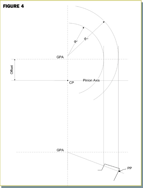
The crown-type HRH has teeth with depthwise tooth taper: the gear member pitch angle and (coincident) face angle are 90 degrees to the axis, but there is a small dedendum angle on the gear (the angle between the pitch line and root line). So the root angle is slightly less than 90 degrees. The mating crown-type HRH pinion, due to parallel clearance, has a corresponding small face angle. From the cross-sectional view, derive the plan view of the gear (figure 4).
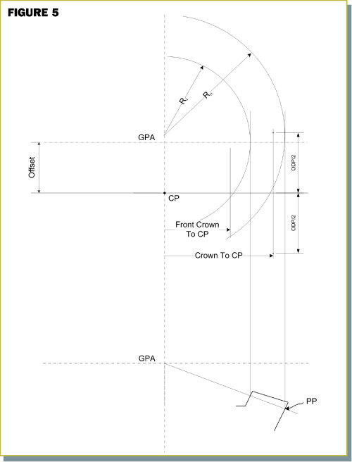
Draw a horizontal line representing the pinion axis at a dimension from the gear center equal to the offset value. Strike a normal (“toe-end normal”) to the pinion axis at a dimension equal to the front crown to crossing point. Strike a second normal (“heel-end normal”) at the crown to crossing point dimension. Mark a point (the crown point) on this second normal corresponding to the pinion outside diameter, or ODP (figure 5).
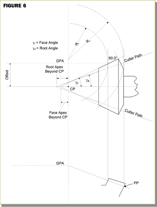
Locate the pinion “face apex beyond crossing point” on the pinion axis. Connect this point with a straight line to the crown point. This should be at an angle equal to the pinion face angle. Draw a solid line on the portion connecting the toe-end normal to the heel-end normal to create the pinion face. From the crown point, at an angle normal to the pinion face angle, drop a line for the tooth heel end. Locate the “root apex beyond crossing point” on the pinion axis. From this point, at the pinion root angle, draw a dotted line connecting the toe-end and heel-end normals to complete the root line and pinion standard theoretical form. Duplicate the construction for the other side of the pinion (figure 6).
To add the pinion to the gear cross-sectional view, the important first step is to locate the pinion axis. On the gear axis, locate the point that corresponds to the value of the gear “crown to crossing point.” Through this point, strike a horizontal line that is the pinion axis. Drop down the pinion construction from the above plan view to complete the initial layout (%%layoutguides0306fig7%%).
The initial layout now serves as the reference frame for completing the blank design. We hope this article has been helpful for the design of your bevel gear sets. Hopefully you can now move forward with the rest of your application design and communicate your needs more effectively with your gear suppliers.


