


In a customer-driven pursuit of design concept solutions to make broaching relevant to lean manufacturing, the lower lot sizes associated with reduced work in process, and one-part flow manufacturing goals, American Broach & Machine has developed a broaching machine designed to address customer complaints with traditional broaching machines. Our customers want a broaching machine that’s faster, simpler, cheaper, and in a small convenient package. Our tabletop design, where a broach-cutting tool is pulled down through the broaching table, is a clever merging of technology with physics to meet this need. Our design melds known and new concepts together to affect the solutions our customers have been requesting but haven’t been able to find. Another object of our invention is to simplify the construction of such machines, and to provide a broaching machine that will be effective in operation and occupy very little floor space.
Our invention and improvement in vertical pull-down broaching technology consists of certain novel features that will be evident to the reader when referencing the accompanying illustrations. It is implied and understood that many of the concepts in our machine are present and have been used in broaching applications for decades, with the exception of the “teach” function for adjusting stroke and the elimination of the machine frame as the support for force resistance through bulk, girth, and guideways. That being said, no one ever put the drive system completely under a table in such a compact manner, giving the user access to a flat part locating surface with no obstructions, to produce a small, light, tabletop broaching machine, quickly adaptable to many applications in broaching. These features are detailed here and in the accompanying illustration, describing 16 clever features or concepts brought together in our design. It is our contention that these features can be used together or in incomplete combinations, variously combined or arranged to achieve the object of our stated efforts within the scope of our claimed patent.
This machine was designed to minimize space and capital equipment cost, while providing speed and performance for manufactures with smaller lot sizes, constrained space, and a need for an efficient, quick-change broaching machine. The machine will initially be offered in 24”, 32”, 36”, and 40” stroke lengths, from two to 10 tons in power, and with electromechanical dual screw drive systems.

Design/Operation Details
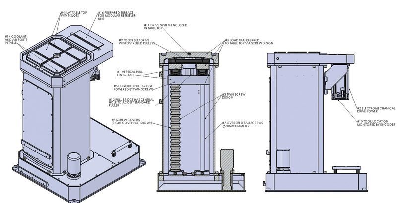
In this machine—see (1) in the accompanying diagram, with the steps that follow also numbered—the cutting tool is moving in the vertical plane for the best use of gravity and physics to produce better-quality parts and longer tool life compared to horizontal broaching. This orientation also uses less floor space (#1 reference patent #1,376,708 May 3, 1921, F.J. Lapointe). (2) The use of electromechanical drive power eliminates the cadence (pounding) associated with horizontal broaching that results from the compression and expansion of the hydraulic oil as the cutting forces vary during the broaching process. (3) The twin-screw design provides smooth, steady power, increasing tool life and part quality while reducing the perishable tooling cost per part (#3 reference patent #3,103852 Sept 17, 1963, O. W. Bonnafe).
American Broach & Machine Company’s design features (4) a simple, flat tabletop broaching area with crossing “T“ slots to accommodate fast, accurate setup. This one-piece solid tabletop has been designed to attach to a fabricated main box assembly that is mounted on top of a coolant sump box base. This modular design keeps the cost of build and maintenance service low, while maintaining structurally robust physical attributes by design without the traditional girth used by broaching machines. In our design (5) the load distribution is transferred to the tabletop directly through the twin roller screw assembly without the traditional machine ram, box way, rails, carriage, guide rods, or bearing cars. This eliminates the need for a heavy machine frame and allows for a modular box design that meets our customers’, need criteria.

Pulling as opposed to pushing the broach tool is recognized as being very accurate. The machine features (6) a unique unguided pull bridge powered by two spindles (roller or planetary) that are mounted under the table in a compact design, (7) utilizing oversized spindles to eliminate the need for guide rods or bearing ways that will not tolerate being mounted in areas with chips and coolant under the table. (8) The spindles are fully enclosed by clever slide covers to prevent chip interference and coolant damage, all the while fitting into a small space under the broaching table. (9) The spindles are powered by a tooth belt by way of oversized tooth-drive pulleys; this oversizing allows a single motor to drive both spindles simultaneously, and extremely accurately, while not positioning the drive belt in line in the space where the cutting tool travels. (10) Tool location is monitored by motor rotation position tracking by a simple encoder. (11) The entire drive system is cleverly enclosed and sealed into the hollow bottom under the broaching table (plenum) and fully protected from the chips and coolant.
Protecting the drive system from the coolant, chips, and dirt is very important in the “under the table” drive system design of our machine. (12) The pull bridge has a central hole bored and threaded to accept American Broach standard pull heads (these are an industry standard today that were invented by ABM in the 1940s, Patent # 2,392,747 January 8, 1946, F. J. Lapointe). The two-inch, eight threads are on the exact centerline of the dual spindles; this placement optimizes load forces into a straight line, which eliminates machine stress and possible deflection.
Quick changeover between parts to accommodate small production lots is an important concept behind our machine design. One such feature is a convenient panel providing easy access for changing the standard pull heads. While seeking other ways to accommodate quick change—and, more importantly, to protect the stroke length setting switches and stops that would normally be required, and are undesirable to place under the table with all the coolant, chips, and dirt—we have developed (13) a quick “teach button” feature. This adjusts that stroke for the length of the tool, automatically and in seconds, rather that using stops and switches that do not hold up well in the under-table environment.

Additionally, it takes several minutes of trial and error to set traditional stops. Now, with a simple visual setting, the stroke length is set and no data entry or measurement is required. The operator simply lowers the broach tool in the teach setup slow movement mode, and when the tool is just below the part nest the teach button is pushed. Each stroke will now stop at that exact spot. fig. 4
Many convenient standard features have been incorporated into our design, such as (14) coolant and air ports designed into the tabletop (plenum) for ease of distribution in various applications. (15) A removable ring type splash guard is delivered with each machine. This ring splash guard lifts off in seconds to accommodate large or irregularly shaped parts that can’t easily be broached on conventional machines, adding to the machine’s adaptability.
As an option this machine is offered with a simple retriever attachment that will allow for complete auto cycle without requiring the operator to handle the broaching tool. (16) This modular retrieve unit can easily be attached via a precision prepared surface that is part of the tabletop. The retriever is quickly and accurately located with keys and standard t-slots to ensure that the retriever is on centerline with the pull head. The unit is electric motor and belt driven, fully enclosed, utilizing a scale for location control and an electric controlled detent type retriever head. Once the retriever is mounted and bolted down, all you need to do is plug it in and it’s ready to use.
What sets American Broach & Machine Company’s tabletop electromechanical broaching machine apart from the rest is the fact that we have combined all of these recognized best broaching concepts and developed solutions together under the table, with a compact footprint and simple design, all at a very reasonable price.


