


Automotive transmission gear noise has received increased attention in recent years. The phenomenon is considered as a major noise source in the automotive industry. It is perceived as a vehicle-built quality issue and is caused by impacts of the loose (unengaged) meshing gear teeth pairs through their backlash. The problem is also exacerbated by the oscillatory crankshaft vibration signal (engine order vibrations), which has a greater poignancy with the higher torque fluctuations of diesel engines at multiples of engine order vibration [1, 2]. Modern downsizing philosophy has led to compact transmissions, thus a greater tendency for the interactions of the loose meshing gear pairs. As the result, the engine torsional oscillations, resident on the transmission input shaft, exacerbate the teeth pair impacts through their lubricated conjunctions [3, 4]. The accelerative nature of these impacts causes radiated noise, which is widely termed as gear rattle [5].
 A large volume of numerical analyses has been reported, particularly for parallel axis gearing systems. Most analyses consider dry contact of meshing pairs, which is representative of highly loaded cases, where elastohydrodynamic conditions may be reasonably approximated by the classical Hertzian theory [6, 7]. Other analyses have included the effect of lubricant in the contact, which is particularly important for lightly loaded contacts, where a hydrodynamic regime of lubrication would be prevalent, such as in the case of idle gear rattle [1, 8–10]. The contact stiffness under lightly loaded hydrodynamic conditions is well below that obtained through use of the classical Hertzian theory. In addition, the temperature dependence of lubricant viscosity significantly affects its load carrying capacity, as well as its shear characteristics, thus influencing gear dynamics [3, 9, 10].
Much attention has been paid to the estimation of radiated noise from meshing gear pairs with the aim of determining a threshold for the onset of unacceptable gear rattle. These have been mostly experimental, often involving determination of coefficients of restitution to describe the effect of lubricant damping through its squeeze film motion [11], as well as any hysteretic elastic deformation of the impacting solid surfaces. Using a torsional vibration model, gear rattle noise was calculated for a 5-speed gearbox, employing the main design parameters and use of various empirical formulae [12]. Following an optimization study, the gear noise was shown to be reduced by 14 percent. The influence of different parameters on lubrication conditions and structure-borne noise of gear transmissions was also studied by Fietkau and Bertsche [13]. This enabled direct determination of structure-borne noise for the rattling loose gear pairs, as well as for the loaded gear pairs. The findings were validated experimentally.
Radiated structure-borne noise from a gearbox was calculated using three-dimensional Finite Element Analysis (FEA) of the structure, combined with the Rayleigh integral method [14]. A simplified gearbox, excited internally by the gear teeth meshing stiffness was used, where the vibro-acoustic coupling between the elastic housing, the air-cavity and the free acoustic field was considered. Mucchi et al. [15] presented a method for determination of noise and vibration analysis of gear pumps, comprising a combination of numerical analysis and experimental measurements. The numerical method included lumped parameters, integrated with FEA and Boundary Element Method (BEM). The lumped parameter model comprised loaded bearings and gears, while the FEA was used for the casing and plates. The use of BEM resulted in the prediction of the emitted noise levels. The experimental measurements included inertial acceleration and acoustic pressure, which were verified through simulation results.

A model relating the acceleration response of chain drive components (sprocket teeth against chain rollers) to the generated sound was developed using finite element techniques and numerical schemes by Zheng et al. [16]. Sound pressure levels at different locations on a virtual cylindrical surface around the chain were evaluated and validated against experimental measurements, showing good agreement. The work was based, to a large extent, on that reported by Yufang et al. [17], where the radiated sound from the impact of two rigid cylinders was calculated through use of Hertzian impact theory and verified experimentally.
In this paper, an analytical method to predict the airborne radiated noise from the meshing gear teeth under light loads is presented. The method is based on rigid body dynamics, coupled with hydrodynamic lubricated contacts, as well as far field sound pressure calculations. This analytical approach has not hitherto been reported in literature. In the following sections, the methodology for sound radiation predictions is presented initially, as well as a flowchart for the numerical calculations. The experimental configuration is then described, followed by analytical results and discussion. The numerical predictions show good agreement with the experimental measurements obtained from a single stage gearbox.

Methodology
The gear pair system studied is shown schematically in Figure 1. The entire physical assembly is depicted in Figure 3. The input pinion shaft is driven by an electric motor. The gear wheel is mounted onto a shaft and is resisted through generated friction at the supporting bearings. The spur gear pair is modeled by a single degree of freedom rotational inertia (gear wheel) with the pinion’s motion known a priori. (This is a kinematic non-holonomic constraint; see “Results and Discussion” section.) The remaining 5 degrees of freedom of the gear wheel are constrained because the associated motions are deemed negligible due to the light loads transmitted. The equation of motion for the gear wheel (Figure 1) is obtained as:

where Ig is the gear wheel inertia with jg being the corresponding rotational degree of freedom. Fw is the meshing teeth contact force. rbg is the gear base radius; Ff is the flank friction with rf being its moment arm. Fp is the bearing generated friction while rs is the outer contacting radius of the output gear wheel retaining shaft. For the lightly loaded meshing of loose gear pairs, flank friction is quite insignificant and may be neglected in the analysis [8]. The tooth hydrodynamic contact force is given by [4, 18]:

Equation 2 provides the lubricant reaction under assumed iso-viscous rigid hydrodynamic regime of lubrication, where the term
![]() is the squeeze film contribution. When
is the squeeze film contribution. When
![]() < 0, the meshing surfaces converge, leading to increased load carrying capacity. Conversely, when
< 0, the meshing surfaces converge, leading to increased load carrying capacity. Conversely, when
![]() ≥ 0 pure rolling and sliding motion occurs or the mating surfaces separate, thus there is no squeeze film effect [19]. The hydrodynamic film thickness under iso-viscous rigid condition is given by:
≥ 0 pure rolling and sliding motion occurs or the mating surfaces separate, thus there is no squeeze film effect [19]. The hydrodynamic film thickness under iso-viscous rigid condition is given by:

The linear bearing friction in the conforming contact of the loose gear wheel bore and its retaining supporting shaft (the gearbox output shaft) conjunction is described by Petrov friction with null Petrov multiplier for an assumed eccentricity ratio of unity (as the film thickness in this conjunction is very thin), thus [19]:

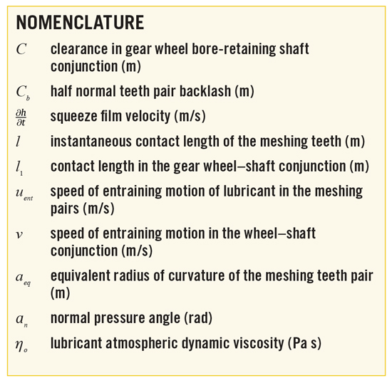
More details regarding Equations 2-4 are provided in references [3, 18, 19]. A brief description of the main variables can be found in the nomenclature.

For the calculation of airborne noise from the meshing gear teeth pairs, lightly loaded impact of an equivalent pair of rigid cylinders is assumed [17]. This assumption is based on the gear teeth shape (spur gears in this case), where the length of the contact line is time invariant (being equal to the flank width of the teeth). The contacting teeth pairs (cylinders) of the pinion and gear may be represented instantaneously by an ellipsoidal solid with equivalent radius of contact, impacting a semi-infinite elastic half-space [8]. The mass of that equivalent cylinder is obtained as:

where l is the flank width, r is the material density of the ellipsoidal solid and aeq is its equivalent radius; subscripts p and g stand for the pinion and gear, respectively.

The duration of a complete impact event is used to define the critical contact time tc employed in this study. In the case of dry impacts between two cylinders (i.e., in the absence of a lubricant film), this is obtained through using the Hertzian impact time. In the examined case of the lubricated teeth, however, there is no clear separation of the teeth surfaces, since there is always a thin layer of lubricant present. Therefore, this should be set equal to the period of the meshing frequency wc. This enables the capture of any fast occurring transient dynamics of the impacting pairs. Thus, in contrast to the previously employed approach for the case of a single impact between cylinders [17], it is assumed that the lubricated teeth are always operating within the critical contact time limit. Thus:

where ri indicates the distance between the center of the tooth (cylinder) and the far sound field location where the ensuing noise level is to be determined. ai is the radius of each cylinder (contact radius of the pinion and gear) while c is the sound speed in the air.
Therefore, the sound pressure in the far sound field can be expressed analytically as [17]:

Details regarding coefficients A, B, D, E, and F are provided in the Appendix A. The variables a, r, and 0 contained in those coefficients take their corresponding values for the pinion and gear. r0 is the density of air and am is the instantaneous acceleration of each impacting cylinder, which is calculated as:

The total sound pressure radiated from two impacting teeth (cylinders) I and II at any arbitrary point (distance r from the impact site) is given by reference [17]:

where the parameters rI , rII , JI, and JII are shown in Figure 2. In the problem examined, subscripts I and II stand for the pinion and gear teeth, respectively. Thus, the radiated noise contribution from each tooth is determined.

The overall radiated noise levels can be calculated as (for more than one pair of teeth in simultaneous contact):

where the subscripts 1, 2, . . . N indicate the teeth pairs in simultaneous meshing action with pref = 20 mPa.

Numerical implementation and programming
The procedure for the numerical calculations comprises:
- Calculation of gear geometric data: number of teeth pairs in simultaneous contact, radii of teeth contact and the speed of entraining motion of the lubricant into the rolling, sliding and normally approaching and departing meshing teeth pairs.
- Estimation of lubricant film thickness using Equation 3.
- Calculation of teeth contact/impact and Petrov friction forces (Equations 2 and 4).
- Solution of the equation of motion (Equation 1) through step-by-step integration algorithm, using Newmark’s linear acceleration scheme, detailed in reference [18].
- Calculation of t’, using Equation 6.
- Calculation of the equivalent mass and the resulting acceleration, using Equations 5 and 8.
- Determination of sound pressure radiation from each impact site at the far sound field, using Equations 7 and 9.
- Evaluation of radiated sound pressure from all the gear teeth pairs in simultaneous contact/impact.
- Transformation of the sound pressure levels in dB units (Equation 10).

Experimental setup
A purpose built experimental rig is presented with a standard spur gear pair configuration, assembled in a semi-anechoic chamber, as shown in Figure 3. The gear pair is run under lightly loaded (unloaded) condition, where the only resisting loads are due to friction generated in the linear bearing supports. The input torque is measured using a torque transducer. The input and output gearbox shafts’ velocities are monitored using dual beam laser vibrometers (Table 1 provides hardware details).
The driving torque is introduced into the system by a small electric motor. The nominal and fluctuating speed components are controlled through a signal generator, capable of producing a fixed voltage offset (nominal speed — DC component) and a superimposed fluctuating sinusoidal component (representing engine order vibrations encountered in vehicular transmissions). In this manner, a simple voltage signal with a clear alternating component can be used to produce the desired operating input speed for the experiment. The AC component of up to 18 Hz can be applied under the setup condition. In practical terms, the setup represents the second engine order vibration (twice the crankshaft speed) of a 4-stroke 4-cylinder engine, operating with the idle speed of approximately 800 rpm (13 Hz), which is representative of modern small size engines. The maximum nominal operating speed of the motor is 2700 rpm, which also falls within the required operating conditions.

The data-logging software was developed in the Labview environment, enabling simultaneous acquisition of the input torque, rotational speeds of the input and output shafts and the employed accelerometer and microphone readings. This is similar to the software, data acquisition, and monitoring of larger powertrain rigs presented in De la Cruz et al. [9]. The experimental setup is used for simultaneous air- and structure-borne noise measurements, thus allowing for direct comparisons between the experimentally obtained values and those predicted through numerical analysis.
Results and Discussion
Two nominal operating speeds are employed in the study: 675 and 1320 rpm. These span the idle and low speed, low gear creep (partially loaded) rattle conditions in small b-class modern vehicles. In both cases, the influence of harmonic excitations residing on the input gearbox shaft is also considered, as such oscillations have shown to adversely affect the propensity to rattle [1, 3-5]. In this manner, gear vibration conditions of low and high severity can be studied in more detail. Table 2 presents the employed tests conditions.
Figure 4 shows typical time histories of the input conditions used. These velocity time histories were experimentally obtained, using a dual beam laser vibrometer (as previously described). It can be noted that tests no. 1 and 2 show clearly distinct behaviors, characterized by the imposition of 13 Hz oscillations in test no. 2. It is also noted that the same test exhibits a slightly higher nominal speed than the targeted 675 rpm. This is because of the experimental control mechanism and is not expected to cause significant variations in the physics of the examined system.

Figure 5 presents the experimentally measured torque time history at the location of the input shaft and its numerical equivalent, predicted by the gear pair dynamic model. The inputs to the model are the angular displacement and velocity of the pinion. The generated contact reactions and the resisting torque are calculated using Equations 1 and 2 in an iterative manner. The comparison made in Figure 5 depicts the degree of conformity of the numerical predictions with the actual measured torque using the experimental rig. The mean torque values obtained from the plots are given as 0.129 Nm for the numerical predictions and 0.103 Nm from the experiment. The higher predicted torque spikes may be as the result of instances where the assumed iso-viscous conditions embodied in Equation 2 are momentarily breached (i.e., piezo-viscous hydrodynamics encountered). This can occur with the approaching meshing teeth flanks resulting in thinner lubricant films, which may be sustained under iso-viscous conditions. This hypothesis is further discussed when the sound pressure levels are investigated later.
Figure 6 shows the numerical and experimental output speed time histories of the loose gear wheel for test no. 4. These results are discussed in conjunction with those of Figure 7 and Figure 8. The first point to observe is the magnitude of the measured output values in comparison with those of numerical predictions, which are consistently higher than those measured. This can be related to the slightly higher values of the input torque (Figure 5). Nevertheless, these differences are within 2-3 percent and may be as the result of an assumed kinematic input condition to the numerical model, whereas in reality the input oscillatory behavior has a transient dynamic nature.
Figure 7 and Figure 8

show the predicted and measured vibration spectra of the gear wheel speed. In this case, the Fast Fourier Transform (FFT) quantity employed is the Power Spectral Density Time Integral Square Amplitude (PSD TISA). It is given by:

where nsize stands for the data set size, Re for the real part of the FFT, Im for the imaginary part of the FFT and Dt for the sampling interval (time step).
The main spectral contribution frequency is at the imposed forcing frequency of the gearbox input shaft, transmitted through impact of the resident pinion with the gear wheel. This is at 13-14 Hz, which is superimposed by the frequency generator. The fact that no other major contributions are found is a sign of the model robustness, indicating that the physics of the system are adequately captured. In this particular case, the meshing frequency contributes little because of improper meshing at low transmitted forces and repetitive impacts. This is the typical conditions encountered in vehicular transmission rattle [3-5].
The radiated airborne sound as the result of the repetitive impacts can now be obtained and comparisons made between the numerical predictions and experimental measurements. Furthermore, comparison can be made between low and high levels of vibration, i.e., test no. 1 against test no. 2 or test no. 3 against test no. 4.

Figure 9 presents (indicative) FFT spectra of the numerical and experimental radiated sound pressure time histories for tests no. 1 and 2. Although it can be observed that the experimental results contain significant noise, they exhibit the main expected phenomena (similar to those in the numerical results). The numerical results for test no. 1 (Figure 9a) show the gear teeth meshing frequency (at around 226 Hz), as well as its second harmonic around 453 Hz. The lower frequency observed (49 Hz) is the mains supply frequency. This is unavoidably present in the input shaft rotational speed captured by the laser vibrometer (this is used as an input to the model, thus the presence of the mains frequency). The meshing frequency as well as its second harmonic are evident in the experimental measurements, contaminated by heavy modulations due to the speed of the shafts (Figure 9b). When the forcing frequency of 13-14 Hz is introduced in the input shaft signal (test no. 2, Figure 9c and Figure 9d), this is evident in both the numerical and experimental spectra. The model predicts better (intense) teeth meshing conditions compared with the experiment, as is indicated by the energy carried by the forcing frequency in both cases. However, the same fundamental frequencies are observed in both cases (the meshing frequency and its harmonics, the forcing frequency and the mains frequency in the case of the model), which is an evidence for the robustness of the employed method.

In order to directly compare the outcome of the numerical model with the experimental measurements, the Equivalent Sound Pressure Level values are calculated for the four examined tests as:

The Leq values are presented in Table 3. As a general trend, it can be seen that the numerical model over-estimates the Leq values as a consequence of the severe meshing gear teeth impacts. This is in line with the previously stated remarks concerning the higher torques noted in the numerical results, which yield higher impact velocities and thus greater impact energies. Thus, higher sound levels are predicted than measured. It can also be noted that for tests no. 1 and 3, the difference between the numerical and experimental results is slightly larger compared with the other two tests (as highlighted in the Leq values in Table 3). It seems that once the sinusoidal harmonic is introduced in the input signal, the numerical model does not exhibit as large a difference in the level of output vibration as that observed experimentally. Nevertheless, the overall predictions and trends conform well with the measurements with small percentage deviations.

An advantage of numerical analysis is in evaluating performance measures that are otherwise difficult to estimate using an experimental rig, such as lubricant film thickness in teeth pair conjunctions. This is important in terms of potential wear and fatigue issues. Figure 10 presents the lubricant film thickness for tests no. 1 and 2. Test no. 2 corresponds to a high impulsive vibration case with imposed harmonic input signal. One would expect a greater extent of variation in the film thickness under such conditions [9]. However, double-sided impacts (as an indication of severe conditions) are not encountered between the impacting teeth pairs, as the backlash limit is just breached as shown in the figure. Therefore, establishing the degree of severity of gear impacts and sound emission becomes difficult, when compared with the film thickness time history of non-impulsive conditions of test no. 1 (with no harmonic input component). Both time history plots appear to be quite similar, in terms of magnitude and frequency content. This shows that the film thickness variation alone is insufficient to ascertain the level of ensuing vibration. The reason for this is the low damping of lubricant film, particularly when very thin films are encountered. Dareing and Johnson [20] demonstrated this characteristic of thin lubricant films in experiments with contacting wavy surfaced discs. Mehdigoli et al. [21] carried out detailed numerical analysis of the same case as that of Dareing and Johnson [20] and found lubricant film damping is minimal with a decreasing film thickness and increasing contact force, yielding elastohydrodynamic regime of lubrication. Therefore, it is necessary to study the accelerative motion of the gear wheel, which is a faster changing output signal.

Figure 11 presents the FFT spectra of the acceleration time history for tests no. 1 (non-impulsive) and no. 2 (impulsive). It can be seen that in the case of the former, there are spectral contributions at the first and second harmonics of the teeth meshing frequency (227 Hz). This is a characteristic response of orderly meshing. The contribution at 52 Hz is the mains contribution, captured by the input velocity measurement. In the FFT spectrum of test no. 2, the forcing frequency at 13 Hz is evident, while the contribution at the meshing frequency is clearly reduced, with the second harmonic almost imperceptible. This is indicative of improper meshing caused by an impulsive input. Therefore, a good measure of severity of radiated noise is the interruption of orderly meshing as perceived by reduced spectral dominance of the meshing frequency and its harmonics. This conclusion is in line with the findings presented in reference [9].
Conclusion
An analytical methodology to predict gear teeth airborne sound pressure levels is presented. A comparison between the numerical predictions and experimental measurements for a single stage gear pair exhibit similar qualitative trends in the frequency domain and quantitatively by calculating the Equivalent Sound Pressure Levels. It is shown clearly that the presence of harmonics in the input shaft speed induce higher gear noise emissions. Furthermore, the analysis proves the hypothesis that an orderly meshing pairs’ vibration spectrum is dominated by their meshing frequency and its harmonics and result in lower gear noise levels. The analytical predictive tool can be used by design and development engineers for rapid prediction of gear noise of multi-speed transmissions for a variety of applications at the conceptual design stage.
References
- Russo R., Brancati R., Rocca E. Experimental investigations about the influence of oil lubricant between teeth on the gear rattle phenomenon. J Sound Vib 2009; 321:647–61.
- Lu J.W., Chen H., Zeng F., Vakakis A., Bergman L. Influence of system parameters on dynamic behavior of gear pair with stochastic backlash. Meccanica http:// dx.doi.org/10.1007/s11012-013-9803.
- Theodossiades S., Tangasawi O., Rahnejat H. Gear teeth impacts in hydrodynamic conjunctions promoting idle gear rattle. J Sound Vib 2007; 303(3–5):632–58.
- Tangasawi O., Theodossiades S., Rahnejat H. Lightly loaded lubricated impacts: idle gear rattle. J Sound Vib 2007; 308(3–5):418–30.
- Dogan S.N., Ryborz J., Bertsche B. Design of low noise manual automotive transmission. Proc Inst Mech Eng, Part K: J Multi-Body Dynam 2006; 220:79–95.
- Chen Z., Shao Y.M., Lim T.C. Non-linear dynamic simulation of gear response under the idling condition. Int J Automot Technol 2012; 13(4):541–52.
- Ottewill J.R., Neild S.A., Wilson R.E. An investigation into the effect of tooth profile errors on gear rattle. J Sound Vib 2010; 329:3495–506.
- De la Cruz M., Theodossiades S., Rahnejat H. An investigation of manual transmission rattle. Proc Inst Mech Eng, Part K: J Multi-Body Dynam 2010; 224:167–81.
- De la Cruz M., Theodossiades S., King P., Rahnejat H. Transmission drive rattle with thermo-elastohydrodynamic impacts: numerical and experimental investigations. Int J Powertrains 2011; 1(2):137–61.
- Tangasawi O., Theodossiades S., Rahnejat H., Kelly P. Non-linear vibro-impact phenomenon belying transmission idle rattle. Proc Inst Mech Eng, Part C: J Mech Eng Sci 2008; 222(10):1909–23.
- Kadmiri Y., Rigaud E., Perret-Liaudet J., Vary L. Experimental and numerical analysis of automotive gearbox rattle noise. J Sound Vib 2012; 331(13):3144–57.
- Bozca M., Fietkau P. Empirical model based optimization of gearbox geometric design parameters to reduce rattle noise in an automotive transmission. Mech Mach Theory 2010; 45(11):1599–612.
- Fietkau P., Bertsche B. Influence of tribological and geometrical parameters on lubrication conditions and noise of gear transmissions. Mech Mach Theory 2013; 69.
- Abbes M.S., Bouaziz S., Chaari F., Maatar M., Haddar M. An acoustic–structural interaction modelling for the evaluation of a gearbox-radiated noise. Int J Mech Sci 2008; 50:569–77.
- Mucchi E., Rivola A., Dalpiaz G. Modelling dynamic behaviour and noise generation in gear pumps: procedure and validation. Appl Acoust 2014; 77:99–111.
- Zheng H., Wang Y.Y., Liu G.R., Lam K.Y., Quek K.P., Ito T., et al. Efficient modelling and prediction of meshing noise from chain drives. J Sound Vib 2001; 245:133–50.
- Yufang W., Zhongfang T. Sound radiated from the impact of two cylinders. J Sound Vib 1992; 159:295–303.
- Rahnejat H. Computational modelling of problems in contact dynamics. Eng Anal 1985; 2(4):192–7.
- Gohar R., Rahnejat H. Fundamentals of tribology. London: Imperial College Press; 2008.
- Dareing D.W., Johnson K.L. Fluid film damping of rolling contact vibrations. Proc Inst Mech Eng, J Mech Eng Sci 1975; 17(4):214–8.
- Mehdigoli M., Rahnejat H., Gohar R. Vibration response of wavy surfaced disc in elastohydrodynamic rolling contact. Wear 1990; 139(1):1–15.
Acknowledgements
The authors would like to acknowledge the support of Engineering and Physical Sciences Research Council for funding of the Automotive Transmission Rattle Project EP/D050332/1, Ford Motor Company for sponsorship of the research funded under their University Research Program (URP) and the Technology Strategy Board (TSB) and Romax Technology Ltd for the Knowledge Transfer Partnership Scheme 001293. The authors would also like to thank Dr. Stephen Walsh for the useful discussions related to the acoustics part of our work.
This is an open access article published by Elsevier under the Creative Commons Attribution license (CC by 4.0) — creativecommons.org/licenses/by/4.0. Theodossiades, S., De La Cruz, M. and Rahnejat, H., 2015. Prediction of airborne radiated noise from lightly loaded lubricated meshing gear teeth. Applied Acoustics, 100 (December), pp. 79–86. Available at: doi:10.1016/j.apacoust.2015.06.014.
Appendix A


![]()


