


Problems are often encountered in the design of automotive drive axles, since hypoid gear sets are very sensitive to the precise contact conditions. Assembling test rigs is expensive and time consuming, while Finite Element Analysis of the complete system can be problematic due to non-linear contact. This paper describes a numerical simulation method to predict the system deflections and misalignments in a loaded axle assembly. A fully-coupled, non-linear algorithm has been developed to analyze the cage/shaft/bearing/gear/carrier system. Results of the analysis are converted into the four displacement and misalignment parameters that are standard to hypoid gear design and analysis. Good correlation was obtained between the analysis results and test rig data.
Introduction
Hypoid gear systems are used in cross-axis, right-angle drive systems and are extensively applied in rear-wheel drive vehicles. Their location means that any noise generated can easily find its way into the passenger compartment. Naturally, the durability of a hypoid gear set also needs to be maximized.
The performance of the hypoid gear set is adversely affected when the alignment is not ideal. This could be due to manufacturing errors, but in any system the forces generated under loaded conditions inevitably lead to system deflections that affect the alignment.
Previous efforts have focused on the generation of the shape of machined gears and the optimization of the mesh contact patterns by applying tooth contact analysis [1, 2, 3]. However, this approach is only useful if the actual alignment conditions are known.
For a long time, engineers have relied upon test rigs to measure the system deflections in loaded assemblies and the parameters that need to be measured have been previously defined [4]. These are used as an input to the tooth contact analysis (TCA) that deals with the tooth contact conditions in the gear mesh. However, testing is time-consuming, expensive, and cannot be used in the optimization of a design.
An alternative is to generate an analysis model of the complete system. The most commonly used tools are based on Finite Element Analysis (FEA). FE analysis is effective for much of the system, but problems arise when the engineer attempts to model the non-linear, load-dependent stiffness of the rolling element bearings. Again, the process is slow and is not suitable for practical design exercises.
This paper outlines a numerical simulation method to predict more efficiently the alignment conditions in a loaded axle assembly. A reduced stiffness matrix (which can be created by most commercial FEA packages) is used to model the differential cage and the carrier, while the shafts are modeled using beam finite elements.
The analysis also contains specialist analytical models to calculate exactly the non-linear behavior of the bearings. This “hybrid” approach allows a speed of modeling and analysis which means that, for the first time, analytical results are available as an input early in the design process. Comparison with test data confirms that the displacement parameters can be successfully predicted.
Test-Based Methods for Deriving the Alignment Parameters
The significance of the operating alignment of a hypoid gear set has long been recognized. The first attempts to create an analytical tool for predicting the effect of alignment focused on the gear mesh itself. Tooth contact analysis methods were developed that studied how the gear would perform under a range of operating conditions.
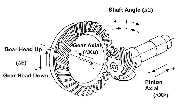
It is necessary to include the operating alignment as an input to the tooth contact analysis. Standard test procedures were therefore developed to measure specifically defined parameters [4]. The four standard parameters, which are shown in Figure 1, are defined as follows:
E = Change in hypoid drop
∑= Change in angle between the two shaft axes
XP = Displacement along pinion axis direction
XG = Displacement along gear axis direction
This method continues to this day, with extensive testing required to confirm the alignment conditions on each design. Without this the tooth contact analysis is unable to optimize the tooth micro-geometry and contact conditions.
The purpose of analysis is twofold. Firstly, it can be used to predict the behavior of a given system or component prior to prototype testing. This means that an engineer can modify the design in software, before metal is cut, in order to obtain improved performance at reduced cost. Secondly, an analysis model that matches test data can be used to gain an understanding of why the system is behaving in a particular manner. This is an essential part of the process if design optimization is to be accomplished.
Given the methods described so far, analysis does not cover the complete process, since prototype testing is still required to provide the “boundary conditions” before micro-geometry analysis and optimization can take place. This represents a “gap,” which limits the performance of the whole design process.
Predicting the Alignment Parameters Using Finite Element Methods
Naturally, engineers have attempted to develop analytical models to predict the alignment parameters in loaded axles. FEA software is common in almost all companies and is the first choice tool for such a task.
FEA is highly effective in modeling complex 3D shapes such as axle carriers and differential cages.
However, the rolling element bearings are an integral part of the axle assembly. Their behavior is non-linear and varies with pre-load and contact angle. Modeling such a system in FE alone requires months of work and extensive experience in FE and bearing analysis.
Even when the model is complete the analysis requires an iterative procedure to find a solution for the non-linear behavior. Each iteration performs the solution of the whole model and therefore takes a long time. To be of use to the design process, the analysis method needs to be speeded up, in order that the engineer may study the effect of changes in operating conditions (torque, reduction in pre-load due to wear) and design modifications.
Developing a Hybrid Model for Rapid and Efficient Analysis
The authors have long recognized the limitations of standard analytical tools and have sought to develop analytical methods that are most appropriate to the application. In describing the behavior of an axle assembly, different methods are required to model the linear behavior of the pinion shaft, carrier, etc., and the non-linear behavior of the bearings.
Non-linear Analysis of the Bearings
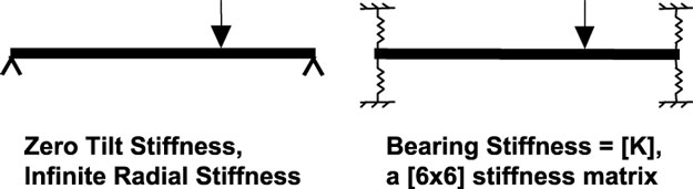
The non-linear stiffness of the bearings is calculated in the analysis, taking into account the applied load, internal geometry, and internal clearance as described in standard literature [5, 6]. When compared with the classic “simply supported beam analysis” (Figure 2), this provides a more accurate calculation of the shaft deflection, and allows three-bearing systems to be analyzed.
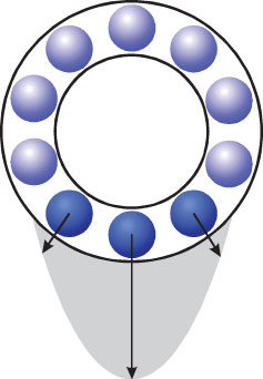
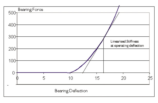
This is an iterative calculation, which is required to calculate the load sharing among the elements (Figure 3) and the load distribution along each of the rollers. The [6×6] stiffness matrix for each bearing is obtained by “linearising” the non-linear behavior of the bearing close to the operating condition (Figure 4). Previous attempts have been carried out to predict hypoid gear displacements including non-linear bearing stiffness [7], although modeling of the whole system has not been undertaken.
Creation of the Overall System Model
The non-linear analysis models of the bearings are assembled with linear analysis models of the other components. The pinion shaft is described using beam finite elements. The differential cage and the axle carrier are complex shapes. 3D FE models are created and the reduced stiffness matrices are extracted. These are a standard output from modern FE packages and the method can be found in FEA textbooks [8]. The matrices are assembled with the other components into the system analysis.
The result is a fully coupled system analysis that includes the effect of the loading and deformation of the different bearings on one another (via the housing). The engineer can investigate the effect of pre-load on the bearing performance and, of course, hypoid alignment. This method was initially demonstrated in parallel axis transmissions [9], but has now been extended to axles. Indeed, the sensitivity of hypoid gears to poor alignment highlights the need for such a tool.
Case Study: An Automotive Axle Correlation with Test Data
Rig tests have been carried out by an axle manufacturer to assess the magnitude of the standard misalignment parameters for a particular design. These test results have been used to validate predictions from the analysis method described in this paper.
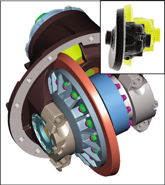
Figure 5 shows a 3D view of an idealized axle, as tested, with a typical deflected FE mesh of the differential cage inset. The rig was fitted with instrumentation to measure the deflection at specified locations and directions [4] on the pinion and crown wheel shafts. Mean and peak values of the indicated deflections were recorded while the axle revolved slowly at various levels of drive and coast torque. Both sets of indicator readings were post-processed to calculate the four mesh misalignment parameters.
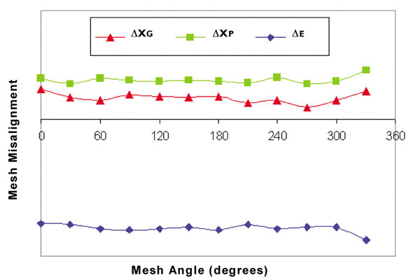
The mean values of recorded misalignment were used for subsequent comparison with the analysis data. Variation of misalignment with mesh angle (Figure 6) can occur where there is substantial asymmetry in the differential cage. In this case there was minimal variation of misalignment with the differential case angular position, both measured and predicted, because the differential cage is largely axi-symmetric.
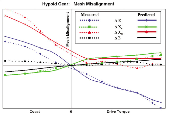
The analysis of the model was carried out at a range of different torque levels, both drive and coast. The analysis was extremely fast, thanks to the use of the reduced stiffness matrix for the carrier and the bespoke bearing analysis models. In this example the static analysis for 12 torque levels was completed in just over two minutes on a 500 MHz personal computer. Figure 7 shows a comparison of the four measured and predicted hypoid mesh misalignment parameters.
Parametric Study into the Effect of Bearing Stiffness
The correlation with test data, combined with the speed of the analysis, means that the simulation becomes a tool that can make a significant impact on decisions early in the design process. However, it has been suggested that the non-linear analysis of the bearings is unnecessary. A simple linear analysis of the shaft and housing deflections could be carried out in a standard FEA package, with the use of a standard, constant bearing stiffness or even a simple support being sufficient.
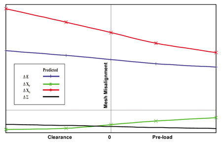
The Effect of Bearing Pre-load on Gear Misalignment—The analytical model was re-run with variations in the pre-load of both sets of bearings. For the sake of simplicity, a single (mid-range) load was analyzed in drive and coast conditions over the range of pre-loads.
A desired maximum pre-load was specified for the bearings. Then an equivalent “pre-load displacement,” required to achieve the desired pre-load, was calculated by running the non-linear shaft/bearing/housing static analysis under zero torque conditions. This given preload displacement was then used for the analysis of the loaded conditions.
By reversing the sign of the given pre-load displacement, a “clearance” condition was created. This was considered of interest as it gives an indication of what can happen if the bearing pre-load varies due to manufacturing variations, temperature changes or bearing wear.
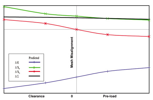
The parametric study showed that pre-load has an important effect on the misalignment values. By moving from pre-load to clearance in the drive condition, three of the parameters varied by between 20 and 240 percent, while the other parameter changed sign completely (Figure 8). In the coast condition, the four parameters varied by between 35 and 250 percent for the same range (Figure 9).
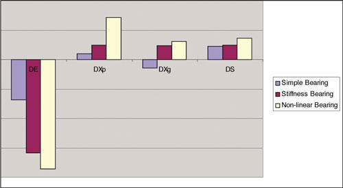
Assessment of Results Obtained using Simple Bearing Models—The final part of the study was to find out the results that would be obtained if simpler models, of the type that could be input into an FEA package, were used in place of the non-linear bearing contact analysis model.
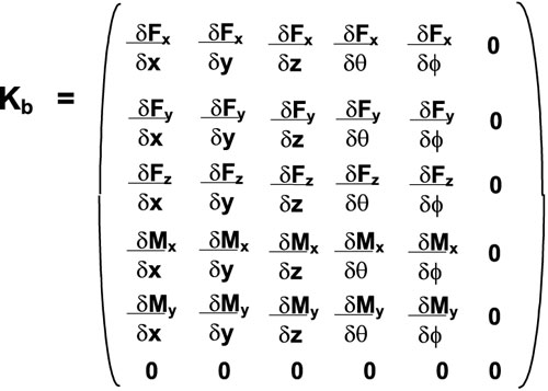
Two further models were created for this purpose. The first model had “simple supports” defined in place of the rolling element bearings. These supports all had high radial stiffnesses (1e12 N/mm) and zero tilt stiffness. For each shaft the bearing that took the higher thrust load was given high axial stiffness, with zero axial stiffness defined for the other bearing. In this model the bearings were located at the “effective load center” of the tapered roller bearings that they were replacing. The second model tried to impart more realistic properties on the bearings. The non-linear bearing analysis finds a compatible set of forces and displacements for each load case and determines a linearized stiffness matrix of the form that is shown in Figure 10. The matrix contains the cross-coupling terms that are required to represent the behavior of a bearing under load. The terms in the sixth row and column are zero, representing the rotational degree of freedom of the bearing about its own axis.
In the simplified model, each bearing was defined with a single radial, axial, and tilt stiffness. Values were taken from the leading diagonal of the linearized bearing stiffness matrix for one of the (mid-range) torque conditions. Since the tilt stiffness of the bearings was included, the bearings were located at the same positions that were used for the non-linear bearings.
Figure 11 illustrates that it is not acceptable to try simplifying the bearing using alternative analysis models, as these cause too much variation in the values of the misalignment parameters. It helps to use a simple linear stiffness model, but even when accurate values are used for the leading-diagonal stiffness terms the absence of the off-diagonal terms causes the results to change.
Another advantage of using a comprehensive bearing analysis is that the variation of bearing life with pre-load can also be investigated. Pre-load reduces gear mesh misalignment, but excessive pre-load reduces bearing life. This is a tradeoff that must be considered.
Conclusion
Noise and durability of any component needs to be optimized, and a hypoid gear set in an automotive axle is no exception. To date, the majority of work has focused on calculating how the micro-geometry of a mesh can be modified to obtain the ideal contact (tooth contact analysis). However, tooth contact analysis is useful only if the “boundary conditions” are known. These include the alignment of the hypoid gear set, which will vary due to loaded deflections of the system as a whole. Indeed, it has long been recognized that misalignment of hypoid gear sets can adversely affect their operation, in terms of both noise and durability. Standard misalignment parameters have been specified which are necessary for tooth contact analysis to proceed. However, no analysis has previously been available to predict these parameters.
This paper has outlined a numerical simulation method that models the complete system and allows prediction of the standard misalignment parameters. Comparison with test data shows excellent correlation. Furthermore, the time required for the analysis means that the simulation can be used effectively at an early stage in the design process. It has been shown that complex parametric studies can be carried out, such as the relationship between bearing pre-load and hypoid misalignment. Simple analytical models of the bearing are insufficient to obtain the required accuracy of analysis.
References
1) Krenzer, T.J. “Tooth Contact Analysis of Spiral Bevel and Hypoid Gears Under Load,” Gleason Works, Rochester NY.
2) Zhang-Hua, F. & Chung-Biau, T. “Kinematic Optimization of Spiral Bevel Gears.” ASME Trans. Vol. 114, September 1992.
3) Litvin, F.L. et al. “Computerized Simulation of Transmission Errors and Shift of Bearing Contact for Face-Milled Hypoid Gear Drive.” ASME Trans. Vol.117, June 1995.
4) Coleman, W. “Analysis of Mounting Deflections on Bevel and Hypoid Gears.” SAE Automotive Engineering Congress and Exposition, Detroit, February 1975.
5) Palmgren, A. “Ball and Roller Bearing Engineering,” Third Edition, SKF Industries Inc.
6) Harris, T.A. “Rolling Bearing Analysis,” Third Edition, John Wiley & Sons, Inc.
7) Savage, M. “Tooth Contact Shift in Loaded Spiral Bevel Gears.” Gear Technology, November/December 1992.
8) Bathe, K. “Finite Element Procedures,” Prentice-Hall, Inc.
9) Harris, O.J. et al. “Predicting the effects of housing flexibility and bearing stiffness on gear misalignment and transmission noise using a fully coupled nonlinear hyperstatic analysis.” Proceedings, Institution of Mechanical Engineers, C577/005/2000. May 2000.


