


For a spur gear as a mechanical element, the design and sketching of the involute guarantees optimum functionality. This paper shows the parametric design of the generation of the involute tooth flanks with driven curves for a spur gear using SolidWorks. The full parametric design of the gear using the SolidWorks global equations tool and general calculation formulas for spur gear dimensions is also presented here. This shows that the professional application in SolidWorks can be used in the development of the gear design so that the user can simply change the variable N (number of teeth) in the tables of global equations to build a new gear. If a different diametral pitch is necessary, this is also possible to adjust from the table of global equations.
Background
For many years, gears have been one of the main components of many different kinds of rotating machinery, and they often work as a critical part in the total function of the machinery [1]. Gears dominate high-power mechanical transmissions, and involute spur gears are widely used to transmit motion and power between parallel shafts. The popularity of involute spur gears is their simplicity in design, ease of manufacture and maintenance, and relatively low sensitivity to errors [2]. In recent years, SolidWorks computer-aided design (CAD) brings together more than 5,000 engineers and designers from across the globe to network, learn, share, and discover the latest in SolidWorks 3D applications and engineering technologies that help millions of users make great designs happen [3]. With the help of this powerful tool for modeling, this paper presents a detailed parametric spur gear geometric modeling using the number of teeth (N) as the main variable for simulation.
The 3D solid modeling has been widely used because of its ease in visualization, generation of manufacturing drawing, and adaptability compared to traditional 2D drafting. However, the modeling process is time-consuming, and many designers do not have the skills to perform such tasks, especially part-by-part or element-by-element. Parametric modeling makes this generating task easy and less time-consuming because basic features and geometric relations are in constant fashion for a specific product [4]. Once the model is finished, one of the principal abilities will be, with a simple parameter change, all of the design adjusts in a way that reproduces a new part with the different shape as a new model with equivalent mechanical characteristics in simulation.
Modeling
Spur gears have teeth parallel to the axis of rotation used in the transmission of motion between parallel shafts. Considered the simplest gear, it is used to develop the primary kinematic relationships of the tooth form. The pitch circle is a theoretical circle upon which all calculations are usually based [5].
The diametral pitch P is the ratio of the number of teeth on the gear to the pitch diameter. Thus, it is the reciprocal of the module in the metric system (ISO). Since diametral pitch is used only with U.S. units, it is expressed as teeth per inch. In general uses:
- Coarse: 2, 2.25, 2.5, 3, 4, 6, 8, 10, 12, 16
- Fine: 20, 24, 32, 40, 48, 64, 80, 96, 120, 150, 200 [5]
Addendum (a): The radial distance from the pitch circle to the top of the gear tooth:
With the equation tool in SolidWorks, it is possible to write all of the global variables and evaluate the dimensions as a calculation page and solve any change if any variable in the formulas change too. A sample of geometric modeling of a spur gear with diametral pitch P = 8, pressure angle of 20° according to AGMA Standard [4], and number of teeth (N) selected arbitrarily is presented. Note: The units managed in the design set are in the U.S. unit system — inch, pound, second (IPS) — with two decimal places. It’s important to get the uniformity in the beginning (see Figure 1).


Next, to write the equation, include the circles as addendum, dedendum, and pitch, and relate the equation with every sketch in the initial draw. Begin with the addendum circle, and make the extrusion to get the initial 3D body. Give the width of the gear a value of 1 inch to get an arbitrary and standard value (see Figure 2).
Then, proceed to make the extrusion of the addendum circle at mid plane, considering 1 inch as a reference for the thickness of the gear (see Figure 3). Managing the extrude in mid plane helps to solve problems during motion, assembly, and finite elements studies, among others.


With the Ctrl 7 key, show the isometric view. Select the front face referent to the front plane of the new body as normal, and create a sketch (see Figure 4).
The next complete sketch includes almost all of the key parametric design. Carefully take each equation in relation to each sketch. Sketch the base circle, dedendum circle, and pitch circle related to its corresponding equation. To make the construction of the base and pitch circle, draw a construction line coincident at the center of the gear and the last point of the addendum circle, as shown in Figure 5.

Involute Properties
An involute curve can be generated as shown in Figure 6. A partial flange “B” is attached to the cylinder “A,” which is wrapped with a cord “def” and held tight. Point “b” on the cord represents the tracing point, and as the cord is wrapped and unwrapped around the cylinder, point “b” will trace out the involute curve “ac.” The radius of the curvature of the involute varies continuously — zero at point “a” and a maximum at point “c.” At point “b,” the radius is equal to the distance “be” since point “b” is instantaneously rotating around point “e.” Thus, the generating line “de” is normal to the involute at all points of intersection and, at the same time, is always tangent to the cylinder “A.” The circle on which the involute is generated is called the base circle [5].

For the parametric driven equations for t angle of the involute curve from point A of the base circle for a 2D sketch, x and y are the following:
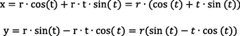
For the model (see Figure 7):
xt = “D2@Sketch2″*0.5*(cos(t)+t*sin(t))”
yt = “D2@Sketch2″*0.5*(sin(t)-t*cos(t))”
where: D2@Sketch2*0.5 is the base circle radius.


The parameters t1 = 0 at the beginning of the base circle and t2 = 0.7 are sufficient to pass the addendum circle.
The alpha angle for involute (αinv):
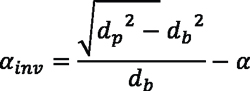
where: α is the pressure angle in radians.
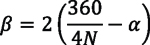
Therefore, the beta angle (β) can be described at the base circle and define the angular distance between Inv1 and Inv2 involute curve.
Include the global variables equations:
Alpha = sqr(dp^2-db^2)/db*180/pi –phi
Beta = (360/(4*N) – alpha)*2
The parametric driven equations for β angle of the involute for the 2D sketch are:
xt = “D2@Sketch2″ *0.5*(cos(-t-2* “D4@Sketch2” *pi/180)-t*sin(-t-2* “D4@Sketch2” *pi/180))
yt = “D2@Sketch2″ *0.5*(sin(-t-2* “D4@Sketch2” *pi/180)+t*cos(-t-2* “D4@Sketch2” *pi/180))
where: D2@Sketch2*0.5 is the base circle radius and D4@Sketch2 is the beta angle sketch.
Figure 8 shows a detail of the model with the parametric driven equation and the parameters t1 and t2.


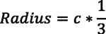
Draw two lines from the centerpoint of the circles and end at the beginning at each involute curve. Make the dimension relation as the measure of half beta angle to ensure uniform changes. Trim the rest of the dedendum circle and centerlines to define the bottom of the teeth. Finally, sketch the bottom radius, which must be 1/3 or 2/3 of the clearance value (see Figure 9).
Cota beta angle = D4@Sketch2 = 360/(4*N)-alpha
Make sure all possible geometric relations are defined to ensure a solid parametric sketch when changes are made.
Extrude cut with the last sketch reference from the sketch plane direction all the way through (see Figure 10).


Make a circular pattern, and be sure the number of instances are related with the global variable N (number of teeth). See Figure 11.
Results
As a result of the parametric design, models can be obtained with number of teeth (N) with the same geometric characteristics and mathematical adaptation according to the global equations. In addition, the regression is included in the design tree to generate a chamfer at 45 degrees, and a bore and keyway to represent the shaft mounting can also be parameterized by shaft standards. Finally, the material steel AISI 1020 can be selected according to the needs of the designer. Figure 12, Figure 13, and Figure 14 show three gears: N = 16, N = 21, and N = 35.


Conclusion
A generic model has been developed with the help of SolidWorks, parametrizing the mathematical size equations. The user can update the model just by modifying the spur gear number of teeth (N). This present study demonstrates the parametric modeling technique for the spur gear. The parametric modeling can automate the way designers perform tasks, especially part-by-part or element-by-element, in the mechanical elements design.
References
- Kiekbusch, Timo at al. Calculation of the Combined Torsional Mesh Stiffness of Spur Gears with Two- and Three-Dimensional Parametrical FE Models. Strojniški vestnik – Journal of Mechanical Engineering. Vol. 57, No. 11, pp. 810-818. 2011.
- Spitas, V. and Spitas, C. Numerical and experimental comparative study of strength-optimised AGMA and FZG spur gears. Acta Mechanica. September 2007, Vol. 193, No. 1, pp. 113 – 126. DOI 10.1007/s00707-006-0384-x.
- Systemes, Dassault. Dassault Systèmes Announces SolidWorks World 2016. bizwire.c66580760, Dallas: s.n., 2016.
- Ruchik D. at al. 3D Parametric Modeling for Product Variants Using Case Study on Inner Ring of Spherical Roller Bearing. Procedia Engineering. Vol. 51, pp. 709-714, India: Elsevier, 2013.
- Shigley, Joseph Edward. Shigley’s Mechanical Engineering Design. USA: McGraw−Hill Primis, 2006. ISBN: 0−390−76487−6.


