


The objective of this research was to develop an optimum preform/blocker forge geometry for a ring gear blank, which would minimize material usage and reduce the number of forging stages by using a volume mapping or other suitable technique. A 2D (axisymmetric) and 3D computer models were used to simulate the forging process (forward simulation) and to ensure proper die fill. The significance of various process parameters such as the intermediate/preform geometry, the optimum aspect ratio of billet, forming temperature, and forming load were determined using the simulation results and volume mapping. The results showed that this research was successful in reducing the number of forging stages, forming temperature, and material wastage. Dies are being manufactured to forge the ring gear blanks based on the new designs. The results of the newly forged geometry will be compared with the simulation results and the volume mapping formulation. American Axle and FIERF jointly funded this project.
Introduction
One of the most widely used computer-aided techniques in simulating and analyzing the metal forming processes including die and preform design is finite element analysis. FEM forward simulation has played a significant role in predicting the deformation flow patterns that have been applied to improve the quality of the products. However, the main role of FEM is to verify the die designs accomplished by using empirical relationships or based on engineering practice [1]. Usually, a number of preforms are needed in order to achieve the final complex shape from the initial simple shape. Forging preform design is computed via backward deformation simulations with procedures similar to die design procedure where the die shapes and process parameters are determined based on the final product shape as well as the material properties requirements. Consequently, forging preform design process using backward simulation has a very crucial function in forging die design process.
Optimizing the entire forging process to obtain the desired goals such as achieving proper die fill, reducing the material waste, reducing the die wear, obtaining favorable grain flow, and the load required can be fulfilled by using adequate and appropriate preform [1]. In the next section, some of the previous research work that has been done in the area of forging preform design process is outlined.
Zhao, X., et al, developed a finite element based sensitivity analysis method for preform die shape design in metal forging by controlling the deformation uniformity [2]. The perform die shape was optimized in order to minimize the effective strain variation of the final forging in order to obtain a uniform deformation. The perform die shapes of H-shaped forging processes in axis-symmetric and plane strain deformation were modeled using this approach.
A new approach is introduced by Yiguo, L., et al. [3], for preform design called Simulation Block Technique (SBT), in which the two half-parts of the forging die are imaginarily separated from their closed position, they move backward from each other in opposite direction of the forward (normal) forging process, so that the initial billet or a preform can be obtained, the model incorporates the use of UBET. A preform design approach that incorporates both FEM-based forward simulations and UBET-based backward simulations was developed by Liu, Q., et al. [4]. Initially, the material flow information is obtained by FEM forward simulation of test preforms, the preform is then designed by UBET based on the information obtained previously, finally, the preform is tested by FEM forward simulation to check whether or not it satisfies the final design conditions. An axi-symmetric gear-blank forging is used to demonstrate the forging preform design, the method was compared with experimental data and showed to be in good agreement. Bramley A., N., [5], has employed TEUBA, which is a UBET-based computer program for the process of forging preform design using reverse simulations. This approach is based on reversing the flow by starting from the desired final shape with the die velocities reversed in such a way that the material at the end of the deepest die cavity is considered to have a free boundary and material flows backward up to certain time step where the dies are separated from the billet, which gives the preform of the process. A finite element-based inverse die contact tracking method to design the perform die shapes of a generic turbine-disk forging process was used by Zhao, G., et al. [6]. Forward simulations were performed while changing the height-to diameter ratio until the optimal aspect ratio of the initial billet was obtained. The simulation’s results show that a net-shape-part can be obtained using the sequence and the new designed preform die shapes as well as obtaining parts with free folding defects and reducing the die wear. An optimization approach for the design of intermediate forging die shapes using backward deformation simulation and design optimization was developed by Han, C., S., et al. [7]. This approach could determine the preform die shapes from the final part shape by imposing constrains on the plastic deformation of the material. The inverse die contact tracking method was presented by Zhao, G., et al. [8]. Both forward and backward finite element simulations to design the perform shapes in plane strain forging were employed.
The sequence of this approach starts with forward simulation of a candidate preform into the final product shape. Kang, B., S., et al. [9] presented preform shapes design in forging of rib-web shaped plane-strain parts by using rigid-plastic finite element method in order to obtain flash-less parts. The preform was obtained by changing the aspect ratio—the height to width ratios of the rib geometry used in the analysis. The preform obtained in plane strain forging was compared with those of axi-symmetric forging rib-web parts.
Volume Mapping Approach Theory
Based on the volume constancy (volume will remain constant or unchanged), the volume mapping approach can be used to derive the velocity fields. These velocities can be evaluated by minimizing the total power of the upper bound elemental technique (UBET), therefore this approach is called the modified upper bound elemental technique (MUBET).
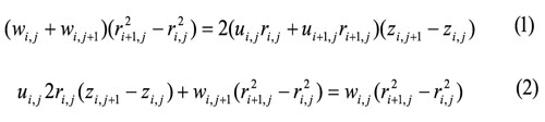
This approach is used to establish a forging preform design strategy in which backward deformation simulation for 2D axisymmetric ring gear blank forging is implemented. For two dimensional (axisymmetric) forging as shown in Figure 1, the velocity fields for a rectangular as well as a triangular element can be derived as given in equation (1) and (2), respectively.

Forging Preform Design Process & Backward Simulation Procedure
The backward deformation simulation process is based on volume mapping approach. Simulation of the inverse deformation process step-wise, is very much like the forward simulation, where the deformed geometry of the work-piece shape is updated using the boundary velocity fields for the current step. In reverse simulations, the boundary velocity field obtained is reversed to calculate the previous incremental geometry of the billet corresponding to the tools moving back through one increment. The procedure is repeated until the desired separation of the dies is reached or until the dies have moved apart to the extent that one of the dies is no longer in contact with the work-piece. The boundary velocities are found by solving the non-linear system of equations after applying the proper boundary conditions. Typically, these equations can be solved using a suitable numerical optimization technique such as Newton Raphson method.


Figure 2 shows a typical cross-section of a final forging with the upper die cavity filled. The process starts by reversing the movement of the upper die as well as the boundary velocities so that both the billet material as well as the upper die move in a direction opposite to that of forward simulations. In this analysis, the profile of the dies and the work-piece cross-section are approximated by straight line segments as shown in (Figure 3). Based on these line segments, the cross-section of the final part will be divided into triangular or rectangular elements. Backward simulations using volume mapping approach can be carried out by reversing the boundary velocity field obtained to calculate the new backward geometry of the billet corresponding to the upper die moving backward (upward) through one backward increment. The main steps of this process can be summarized as follows:
• The final product geometry, finisher die and processing conditions are employed to establish the initial UBET model for the reverse deformation simulation.
• Start with final shape (die filled or almost filled).
• The final shape is divided using straight lines segments into a number of elements rectangular or triangular according to the change of slope of the die-surface geometry.
• Kinematically admissible velocity fields are derived based on step 2, by using volume mapping approach.
• Backward simulation is conducted by reversing the boundary velocity fields.
• A backward step is taken to update the work-piece geometry and die position based on the velocity field from the previous backward step.
• The procedure is repeated until the desired separation of the dies is reached.
• When the stopping criterion is satisfied, the backward simulation is terminated.
• FEM forward simulations is then carried out in order to verify the preform obtained by backward simulations.
Results & Discussion
The forging of a ring gear blank for differentials in automobiles has been considered. A volume mapping technique was used to determine the optimum intermediate shape for forging using backward simulation. The final part is divided into features, which provide an approximated profile consisting of a number of rectangular and triangular elements. It was intended from the present work to achieve proper forging strategy of the ring gear blank forging process through optimizing and reducing the following: (a) material wastage during the multi-stage forging of ring gear blanks; (b) reduce the number of forging (and material handling) stages from three to two, and; (c) reduce the initial billet temperature from about 2100° F to about 1800° F.
These tasks were accomplished by conducting a backward simulation using a volume mapping technique and iterative forward simulation using finite element analysis of the gear blank forging process.
Usually, a number of preforms are needed in order to achieve the final complex shape from the initial simple shape with the optimal properties and geometrical tolerance in metal forming processes [2]. The ring gear blank forging process is a multi stages forging process in which three stages are currently applied in manufacturing the final part. These three current stages were simulated using SuperForge in order to verify the commercial software. Both 2D (axisymmetric) and 3D forging simulations were conducted for this purpose and the results of these simulations were satisfactory with the actual forging process. In order to reduce the number of forging (and material handling) stages, a preform has to be obtained so that the final shape can be attained by only two stages which will reduce the cost and time of material handling as well as the material wastage. Based on volume mapping approach, the kinematically admissible velocity fields are derived and the preform geometry of the second stage forging was obtained by backward simulations. Using the preform obtained by volume mapping approach (Figure 4), the preform is verified by conducting forward computer simulations. The final shape of the ring gear was achieved using the preform.


Several forward computer simulations including 2D (axisymmetric) and 3D forging simulations were conducted in order to optimize the ring gear forging process. The forming temperature was reduced from about 2100° F to about 1800° F, which will have a huge impact in increasing the die life. Also, the material wastage can be reduced from about 5 percent to about 17.5 percent volume reduction. A volume reduction of 5 percent to about 10 percent with about 0.08 in and 0.04 in machining allowance could be achieved. The forming process can be carried out using flash-less precision forging since the die load of the second stage is within the press capacity. The 2D simulation results of the 5 percent volume reduction (case 2) as well as the die load of the two stages are shown in Figure 5 and Figure 6, respectively. Input process parameters of these simulations as well as the load obtained with no volume reduction (case 1), 5 percent volume reduction (case 2), 10 percent volume reduction (case 4), and precision forging (case 3), are summarized in Table 1.


Up to 17.5 percent volume reduction can be achieved by conducting net shape forging with minimally acceptable machining allowance. The first stage forging was performed using different aspect ratios (height to diameter) of the initial stock (billet), it was found from the simulations that the effective plastic strain can be minimized using shorter billets. The simulations results for the net shape forging (case 5) as well as the die load for the two stages are shown in Figure 7 and Figure 8, respectively, also the process parameters of this case are summarized in Table 1.


The forging of a ring gear blank for differentials in automobiles was considered. A volume mapping technique was used to determine the optimum intermediate shape for forging using backward simulation. The final part is divided into features, which provide an approximated profile consisting of a number of rectangular and triangular elements.
Conclusion
In this research, the development of a volume mapping technique was considered to arrive at an optimum preform/blocker forge geometry to minimize material usage and also reduce the number of forging stages of the ring gear blank forging (real problem from industry). A 2D (axis-symmetric) and 3D computer model were used to simulate the forging process (forward simulation) and to ensure proper die fill. The simulations showed that the present method can successfully determine the optimum intermediate (preform) shape of the forging process. From the simulation’s results, it can be conclude that the developed method has the capability to determine the significance of various process parameters such as the intermediate geometry, the optimum aspect ratio of billet, forming temperature, and forming load. Also, from optimizing the different process parameters through the simulations all of the below tasks were met.
• Forging stages were reduced from three stages to two stages.
• The final shape of the ring gear blank was achieved with complete die fill using the preforms obtained by volume mapping approach.
• The initial billet temperature can be reduced to 1800° F.
• Material wastage can also be reduced to about 10 percent.
• The forging process can be carried out using flash-less precision forging since the load obtained was within the press capacity.
• Different aspect ratios were used in the simulations in order to minimize the effective plastic strain, the forming load, and achieving complete die fill.
• The final stage can be carried out using net shape forging in which material wastage can be reduced to about 17.5 percent.
Based on the above, it can be concluded that the developed method has the capability to reduce the number of forging stages. Thus will reduce the material handling, the material wastage as well as reduce the cost of the operation, with the large volume produced of the part in industry.
References
- Altan, T., Oh, S., Gegel, H., Metal Forming Fundamentals and Applications, American Society for Metals, 1995.
- Zhao, X., Zaho, G., Wang, G., and Wang, T., “Preform Die Shape Design for Uniformity of Deformation in Forging based on Preform Sensitivity Analysis,” Journal of Material Processing Technology 128 (2002) 25-32.
- Yiguo, L., Sheng, S., “Reverse Simulation using the Simulation Block Technique and its Application in the Precision Forging Process,” Journal of Material Processing Technology 63 (1997) 244-247.
- Liu, Q., Shichun, W., Sheng, S., “Preform Design in Axisymmetric Forging by a New FEM-UBET Method” Journal of Material Processing Technology 74 (1998) 218-222.
- Bramley A., N., “UBET and TEUBA: Fast Methods for Forging Simulation and Preform Design,” Journal of Material Processing Technology 116 (2001) 62-66.
- Zhao, G., Zaho, Z., Wang, T., and Grandhi, R., V., “Preform Design of a Generic Turbine Disk Forging Process,” Journal of Material Processing Technology 84 (1998) 193-201.
- Han, C., S., Grandhi, R., V., and Srinivasan, R., “Optimum Design of Forging Die Shape using Nonlinear Finite Element Analysis,” AIAA Journal vol. 31, No. 4, April 1993.
- Zaho, G., Wright E., and Grandhi, R., V., “Computer Aided Preform Design in Forging using the Inverse Die Contact Tracking Method,” International Journal of Machine Tools and Manufacturing 36 (1996) 755-769.
- Kang, B., S., Lee, J., H., Kim, B., M., Choi, J., C., “Process Design in Flashless Forging of Rib-Web Shaped Plane Strain Components by the Finite Element Method,” Journal of Material Processing Technology 47 (1995) 291-309.


