


Introduction
Gears that are smaller, cheaper, and equipped with more efficient power transmission are the ongoing objective of gear designers. A significant issue in the design of helical gears is the substantial effect of tooth twisting under load due to torsional and bending deflections of the gears and associated shafts [1]. The elastic deformation experienced in the contact area and gear body shifts the load distribution toward one end of the tooth, greatly increases the maximum root stress and contact stress, and adversely affects the strength of the gears [2].
AGMA 927 [3] outlines an analytical method of determining the bending and torsional deflection of gear shafts and the consequent relative mesh gaps for cylindrical gears. Finite Element Analysis (FEA) is an alternative approach. This paper reports the use of both approaches to a specific gearbox. The differences between modified and unmodified gears are reported, as well as the differences between the results from the two methodologies.
A MATLAB program was developed in this study to perform the necessary calculations according to AGMA 927, as well as combining gear design processes by completing AGMA 2101 [4] power rating calculations. This study was restricted to the analysis of the predominant variable, namely torsional deflection. This decision was based on the fact that for the practical example being analyzed, AGMA 927 showed negligible difference when the bending deflection component across the facewidth of the gear was eliminated.
The software generates a script for input into the FEA program ANSYS Mechanical APDL. This script automatically and directly generates a 3-D model of the gear pair, applies the desired loading and contact conditions, and solves for the stress and deflection. This routine allows for the determination of the suitability of helix angle modification for a subject gear set. It also provides quantification of the optimum modification as well as the benefits for load distribution and peak stress.
Helix Angle Modification
Helix angle modification is a simple flank modification. The modification has the potential to significantly reduce the load intensity and peak stress experienced by compensation for the torsional deflection of the gear tooth (Figure 1).

The implementation of flank modification also allows for a reduction in the peak bending stress caused by the inclined contact lines on helical teeth as the contact approaches the tip of the tooth. By reducing the loading on the relevant side of the tooth and avoiding end contact via helix angle modification, the stress intensity is similarly reduced [5].
The calculations outlined in AGMA 927 facilitate the determination of the torsional and shaft bending deflections and relative mesh gap, and allows for a curve to be fitted to determine the magnitude of helix angle modification required to improve the contact area and load distribution for a subject gear set.
However, whilst AGMA 927 does accommodate torsional and bending deflections of “cylinders” (except for module), it does this independent of any tooth details (e.g. helix angle and tooth shape). While Kissling [6] has shown the benefits of AGMA 927 and its incorporation into ISO 6336-1:2006 [7] with the AGMA 927 analysis being of a toothless cylinder, there is clearly a question surrounding the results generated by AGMA 927.
The FEA performed by the software developed for this study allows for the investigation of tooth shape on the torsional deflection experienced by the helical gears. As a result, this study allows for the comparison of FEA and the AGMA 927 outcomes for torsional deflection for the specific gear analyzed; a comparison which, as noted by Kirov [8] is not always easy to make.
Mathematical Modelling of Tooth Profiles for FEA
The FEA program developed in this study was written in MATLAB. The program has been written such that only a handful of simple user inputs are required, and, specifically, no knowledge of FEA is required.
First, the pitting resistance and bending strength power ratings are determined using the method outlined in AGMA 2101 and AS 2938 [9]. The program then simulates the hobbing process using a number of matrices and iterating loops to generate a numerical representation, for example, of the standard ISO 53 [10] rack. The rack is then translated and rotated around the pitch circle, mathematically simulating the cutting action of the hobbing process, akin to Wilkinson’s [11] method, and Hedlund and Lehtovaara’s [12] method shown as Figure 2.

rotational matrices;  (1)
(1)
This rotational matrix, when multiplied by a matrix of ‘XY’ Cartesian points, rotates the points counter- clockwise around the origin by angle θ. In order to reduce the number of points in the overall geometry, thereby simplifying and reducing the computation time for the FEA, only three teeth on either side of the central contacting tooth are generated with the remainder of the teeth replaced by points on the root diameter of the members.
The initial contact between the pinion and wheel is achieved by determining the minimum angular gap between any point on the pinion tooth and the adjacent point on the wheel. The incremental lead angle is used by the program to generate a three dimensional matrix that represents the pinion and another for the wheel. The two dimensional matrices describing the gears are incremented in the Z direction, rotated by the lead angle and stored in a 3-D matrix.
Finite Element Analysis (FEA)
In order to reduce the number of external programs required and to streamline the operation of the program, the geometry was directly generated within ANSYS Mechanical, using the native command language ANSYS Parametric Design Language (APDL).
The matrices of data points describing the gears, as determined by the MATLAB program, are used by the script to transfer the data into the FEA program and generate the three-dimensional models prior to FEA. The 3-D models of the helical gears by virtue of the robust method used to model them, provide an accurate representation of manufactured gears, with complex involute profiles and helicoid contact lines.

This allows for reliable analysis of the elastic tooth deformation to determine the tooth contact area and load distribution via FEA. The program automatically generates an 8-node SOLID45 element type mesh [13] of the gear geometry (Figure 3). The load from the drive torque is applied evenly to the pinion as a rotational load on each node by the application of a tangential load at each node using the cylindrical coordinate system (Figure 4) akin to the AGMA 927 method.

The example of a pair of 1,500 kW gears shows the reduction in peak stress that is possible through the addition of helix angle modification. As seen in Figure 5, the unmodified gear set was analyzed by the software, with the peak stress recorded.


As AGMA 927 explains, areas with greater mesh gap have lower tooth load, whereas areas with lower mesh gap have higher tooth loads. This is due to the need for the tooth flank to deform elastically in order to close the mesh gap under load. Consequently, an analysis of the mesh gap caused by the deflection of the gear bodies as per AGMA 927 Section 8 (Figure 6) found that the load distribution was very uneven, as the load was significantly skewed towards one end of the mesh.
The load distribution was determined as per sections 9.3 and 9.4 of AGMA 927 with the peak station load found to be 2,934 N, while the average station load was 2,390 N. Hence, the load distribution factor as per Equation 38 of AGMA 927 is:
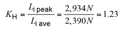 (2)
(2)
The outcome was that there was negligible difference between the load distribution factors when the bending deflection across the facewidth of the gear was eliminated from the AGMA 927 calculations.
Facewidth
The magnitude of the required helix angle modification as a means of compensation for the mesh gap caused by the deflection of the gears under load is determined by the maximum deflection (Figure 6). Following the application of the helix angle modification and prior to the application of the load to the gears, the mesh gap between the gears is shown in Figure 7. While the loading of the unmodified gears causes the deflection shown in Figure 6, the calculated helix angle modification, in combination with the torsional deflection, results in a mesh gap shown in Figure 8.


By compensating for the calculated deflections using helix angle modification, the average mesh gap is significantly reduced, and the load distribution of the gears is improved (Figure 8). Based on the mesh gap values, the peak station load was reduced to 2,523 N, which significantly reduces the load distribution factor, KH, to 1.06 (a reduction of approximately 14%). This would then result in a direct proportionate increase in the power rating of the gear set when AGMA 927 is approved as an AGMA Standard.
The analysis of AGMA 927 by Kissling suggests that crowning may be implemented in addition to helix angle modification to potentially further reduce the mesh gap and improve load distribution.
The method outlined in AGMA 927 contains a number of assumptions and approximations (most notably the use of a toothless cylinder as an adequate representation of a cylinder with gear teeth). The results from AGMA 927, and, therefore, need to be compared to the FEA results, which do not involve these simplifying assumptions. As a result of the “toothless cylinder” representation, there is no ability to investigate different tooth forms. Additionally, in the calculation of the torsional deflection of the gears, an approximation is used in place of integration. It is also assumed that the deflection in the base tangent plane is proportional to the twist angle.
Having noted these and other differences, the outcome of the present study is that for the specific gear analyzed here the assumptions in this case appear to have little effect on the results. Of course, this may not be the case for all examples and further analysis is needed to provide full confidence that this is so more widely.
Nevertheless, it has been a surprise to the authors that there has been no discernible material difference in the results of the two methods in this example. For this to be so, one has to convince oneself that all gear sets can be replicated by cylinders with no reference to tooth shape or form. We would have thought this unlikely, but it is certainly the case here. Clarity must await further investigation.
The FEA was re-calculated to determine the optimum helix angle modification, the results of which can be seen in Figure 9. The calculated optimum modification of 32 microns yields the greatest reduction in peak stress, from 180 MPa to 130 MPa, a reduction of some 28%. It should be noted that this is approximately double the improvement in the load distribution factor as calculated by Equation 38 of AGMA 927.


The results of this method allow for the simple visual confirmation of the effects of helix angle modification and the resultant tooth contact and load distribution. The simplicity of this method for the user helps to bring the improvement of load distribution into the realm of the gear designer without FEA expertise (Figure 10).
Manufacture and Testing of Gears
The example gears in the case study were manufactured in the supply of a custom made 3,000 kW gearbox and reported by the designers Davey and Fay [14] in 2001. The gearbox in question has a double-helical input stage sharing equally the input torque (refer Figure 11). Helix angle modification of 35 microns was applied as a result of the Davey/Fay FEA.


Due to the modified, unmatched helix angle on the gears, the contact determined by the “bluing” process would normally be considered far from satisfactory, with only a small amount of contact seen towards the inside edges of the wheel teeth (refer to Figure 12). However, this test does not take into account the torsional deflection of the gear bodies and tooth structures due to the applied loads and torque.
As a result, following the assembly and installation of the gearbox (Figure 13), the first reduction gear teeth were painted with a commercially available red pressure-based tribological dye in order to determine the contact area under the applied load from the 3,000 kW, 1,500 rpm motor. This specialized tribological dye is designed to break down under pressure, such as the contact pressure occurring between the tooth surfaces in operation.


The contact pattern under the applied loads and torque was easily able to be determined as the dye was removed from the contact areas during operation. The deflection and twisting of the modified teeth due to the applied load, and the resulting change in contact area compared to the “bluing” area can be seen in Figure 14.
The results of the contact testing under load, as well as the fault-free operation of this gearbox for over 12 years, verify the process for torsional deflection compensation to improve tooth contact and load distribution.
Conclusions
The results of the analysis, when compared with the practical results after twelve years of 24/7 operation shows that the proposed method accurately determines the optimum helix angle modification for a gear set. On this occasion, the deflection and resultant helix angle modification determined via Finite Element Analysis is comparable to that calculated using AGMA 927.
This method shows that, although it is not typically easy to directly compare the results of AGMA calculations and FEA due to the different nature of both methods [8], FEA provides a viable alternative to the empirical AGMA 927 method. Due to the potential difficult mathematical rigor of AGMA 927, modification of tooth profiles is often not considered by gear designers. Similarly, it is of interest to note that since 2008, AGMA 927 has not been included in gear design software except for Kissling [6].
The FEA employed here not only provides an alternative to AGMA 927, it also allows a comparison of the accuracy of the approximations and formulae in AGMA 927. In addition, the software determines the subsequent reduction in peak stress, and the calculation of the relevant load distribution factor, KH.
The principal benefits of this analysis method include the ability to simplify the contact analysis and determination of the load distribution by users through the automation of the calculations and FEA. Similarly, the user can visually detect unfavorable tooth contact using the plotted stress results, as well as the improvements caused by the application of helix angle modification.
Importantly, further development of the FEA method [15] would allow for the inclusion into the power rating calculations of thermal contact conditions and other forms of deflection (such as shaft bending, misalignment, bearing clearance and manufacturing errors, potentially leading to an increased understanding of the contact behavior and load distribution of helical gears), and the resultant effect on the power rating of gears Further development would also allow for the expansion of the scope of the FEA to include the full suite of gearbox components to allow for analysis of the entire system.
In the authors’ view, FEA analysis has many advantages for gearbox design. Principally, FEA facilitates the analysis of a gearbox as a complete system in order to identify the ‘weak links’, apply modifications and investigate the flow-on effects of any changes. As such it is a powerful tool for further study into the contact and load distribution behavior of helical gear teeth under conditions such as non-linear load sharing by multiple teeth in simultaneous contact. With this approach, gears can be designed to allow for reduced mass and/or size, for a greater range of applications, as well as the potential improvement in the strength of existing gears.
It will be interesting to see the results of the analysis of gears of varying types with AGMA 927 and FEA to see if the assumptions involved in the former are robust across other tooth geometries and materials of construction. In the meantime, the AGMA 927 has passed this test with flying colors – an impressive result as, in principle, due to the absence of tooth details. The same methodology would apply essentially to spur gears as well as helical gears.
Acknowledgements
The authors of this paper would like to thank the AGMA peer reviewers for their valued feedback provided in regards to the draft of this paper, particularly their comments regarding AGMA 927.
References
1. Ajmi, M., and Velex, P., A model for simulating the quasi-static and dynamic behaviour of solid wide- faced spur and helical gears, Mechanism and Machine Theory, vol. 40, no. 1, pp. 173-190 (2003).
2. Rao, C., and Muthuveerappan, G., Technical Note – Finite Element modelling and stress analysis of helical gear teeth, Computers & Science, vol. 49, no. 6, pp. 1095-1106 (1992).
3. AGMA 927-A01, Load Distribution Factors – Analytical Methods for Cylindrical Gears (2001).
4. ANSI/AGMA 2101-D04, Fundamental Rating Factors and Calculation Methods for Involute Spur and Helical Gear Teeth (2004).
5. Schulze, T., Harann-Gerlach, C., and Schlecht, B., Calculation of Load Distribution in Planetary Gears for an Effective Gear Design Process, AGMA 10FTM08 (2010).
6. Kissling, U., Application and Improvement of Face Load Factor Determination Based on AGMA 927, AGMA 13FTM08 (2013).
7. ISO 6336-1:2006, Calculation of load capacity of spur and helical gears – Part 1: Basic principles, introduction and general influence factors (2006).
8. Kirov, V. 2010, Comparison of the AGMA and FEA Calculations of Gears and Gearbox Components Applied in the Environment of Small Gear Company, AGMA 10FTM05, (2010).
9. AS 2938-1993, Gears – Spur and helical – Guide to specification and rating (1993).
10. ISO 53:1998, Cylindrical gears for general and heavy engineering – Standard basic rack tooth profile (1998).
11. Wilkinson, T.B., A computer program to produce plots of gear tooth profiles and meshing, Undergraduate thesis, University of Wollongong, Wollongong, NSW( 1981).
12. Hedlund, J., and Lehtovaara, A., Modeling of helical gear contact with tooth deflection, Tribology International, vol. 40, pp. 613-619 (2006).
13. Rameshkumar, M., Venkatesan, G., and Sivakumar, P., Finite Element Analysis of High Contact Ratio Gear, AGMA 10FTM06 (2010).
14. Davey, R.J. & Fay, L., PHD Engineering Pty Ltd, Internal Reports – Private Correspondence, 1999.
15. Hipsley, S.R., “Optimisation of Gear Tooth Contact by Helix Angle Modification”, Undergraduate Thesis, Department of Mechanical Engineering, University of Wollongong, Australia (2013).
** Printed with permission of the copyright holder, the American Gear Manufacturers Association, 1001 N. Fairfax Street, Suite 500, Alexandria, Virginia 22314. Statements presented in this paper are those of the authors and may not represent the position or opinion of the AMERICAN GEAR MANUFACTURERS ASSOCIATION.


