


The impact of gear tooth surface roughness and advanced coatings on frictional losses in a gear mesh is of significant interest to the transmission community, as these losses reduce the efficiency of the drive system. Maximizing efficiency to save fuel has long been an objective in vehicle industries. In recent years, the power generation sector has realized that improved efficiency while maintaining robust, long-life gearboxes can improve profit margins. Further, in aircraft applications, these frictional losses are converted to heat that has to be removed from the system. This is done using large heat exchangers and by carrying larger-than-ideal quantities of lubricant onboard the aircraft. Both solutions subtract from the available payload of the aircraft. The impact of lubricant properties on frictional tooth mesh losses is also of interest. More importantly, the gearbox designer needs a simple method to estimate the losses due to friction in a gearbox using known parameters, such as speeds, torques, and lubricant properties. The concept of experimentally computing an “effective coefficient of friction” in a gear mesh that could be utilized in estimating total friction losses in a gearbox was considered a worthwhile effort.
A prior study [1] presented a comparison of frictional losses at the gear tooth flank for three different surface conditions and two lubricants, with the gears operating at three speeds and two different load conditions. The most exhaustive experimental study quantifying gear tooth friction is by Yoshizaki, et al. [2], in which spur gears with various geometries were operated in a power re-circulating test rig and frictional losses were measured. Various lubricants and additives were also evaluated, and tooth surface finishes (Rmax) ranging from 0.5 to 4 μm were considered. Britton, et al. [3] describes another experimental study that specifically evaluated the effect of superfinishing on gear tooth friction on a power re-circulating gear test rig. A 30-percent reduction in frictional losses is measured and documented. In another experimental study on gear tooth friction, Petry-Johnson, et al. [4] measure frictional losses in a power re-circulating test rig operating ground and chemically polished gears with two different tooth sizes in three different lubricants, which were further utilized to define guidelines for the design of gear meshes and transmissions. Martins, et al. [5] experimentally measured the friction coefficient in FZG (ground) gears using two lubricants. Several attempts to model and predict the friction losses [6, 7, 8] are also evident in literature, where the experimental effort is utilized to correlate to analytical results.
Based on the available literature, a comprehensive experimental study to evaluate the effective coefficient of friction at the meshing tooth surfaces, resulting in a parameter that could be utilized in estimating frictional losses in a gearbox — especially as it relates to aerospace gearing — was considered useful. In this study, the variables being evaluated include superfinishing and coated gear teeth against a ground baseline. Two lubricants are also evaluated.
Experimental Setup
The gears evaluated in this study are 6.25-mm face width, 21-tooth, 4.233-module, 20-degree pressure angle, 0.005-mm crown spur gears. These gears were fabricated from AMS 6308 steel, gas carburized, and oil quenched, resulting in a surface hardness of 60–64 on the Rockwell C scale. This experimental procedure was carried out for three operating speeds (5,000, 8,100, and 10,000 rpm), which were determined using a vibration survey.
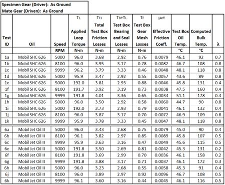
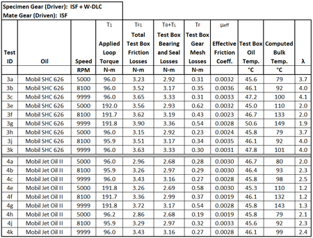
Three different gear tooth flank conditions were used. The first group of test gears utilized an as-ground gear for both the driver and driven gear. The second group utilized a tungsten diamond-like carbon (W-DLC) coated driving gear that was previously isotropic superfinished (REM Surface Engineering’s ISF® Process) against an ISF-driven gear. The third test group utilized an ISF gear for both the driver and driven gear. Two different gear lubricants (Mobil Jet Oil II/MIL-PRF-23699/ISO VG22 and Mobil SHC 626/ISO 12925-1 CKD/ISO VG68) and two different torque levels (96 and 192 N-m) are also considered in this study. All tests were conducted with a nominal oil temperature of 46°C. Oil temperature was controlled by a closed-loop heater/chiller via feedback from a thermocouple on the bearing and gear mesh oil supply line. Test conditions are summarized in Table 1.


After evaluating several alternate experimental configurations to establish the losses (TF1) in the test gearbox, the configuration, illustrated in Figure 1, was selected as the best alternative. A four-square, power-recirculating gear test rig was modified with additional instrumentation for the purpose of this study. The additional instrumentation consisted of incorporating two precision torque transducers (T1 and T2) to measure the input and output to the test gearbox. The third torque transducer (T3) to measure the total losses in the four-square loop had been incorporated earlier. Specifications for the torque transducers used for acquiring measurements T1 and T2 are given in Table 2.

The basis for this setup is that, in a steady-state operation, the torque balance in the test gearbox (T1 driving) sums to zero. That is:
ΣT = 0
T1 – TF1 – T2 = 0
TF1 = T1 – T2
Consequently, the losses in the test gearbox (TF1) can be computed from T1 and T2, with T1 also representing the nominal torque in the four-square loop.
However, TF1 is equal to the total losses in the test gearbox and can be described by:
TF1 = TF + TB + TW + TL
Where:
TF = friction losses at the test gear mesh
TB = bearing losses in the test gearbox
TW = windage losses in the test gearbox
TL = lip seal losses in the test gearbox
TF1 is measured directly in the four-square loop. TB, TW, and TL can be determined through modeling results and zero-load measurements; therefore, a value of friction due solely to the gear mesh TF may be obtained. The effective coefficient of friction (μeff) at the test gear tooth flank is computed for each test condition by defining the following relation:
μeff = TF / T1
Figure 2 shows the experimental setup with the test gearbox on the left and the reversing gearbox to the right. The two torque transducers, T1 and T2, are between the two boxes with the rotors mounted to the shafts and the stators suspended from the structure above. Also visible are the bearing supports between the two gearboxes. The torque transducer, T3, which measures the total input torque to the test rig, is partially visible behind the reversing gearbox.

Surface Characterization
The initial effort focused on characterization of the test gear surfaces. Replicas of the tooth surfaces (tooth space negatives) were first fabricated using surface replication epoxy. The accuracy of this method has been verified to be within 10 percent on ground surfaces, and it improves as the surface becomes smoother. The replicas were analyzed utilizing optical interferometry to obtain surface roughness measurements of the actual ground, superfinished, and coated test gears. Each optical interferometry measurement yielded topography data over a 0.83 mm x 0.83 mm area; Ra and Rz were then computed by analyzing 0.76-mm-long cross-sections of the data. This results in an effective cutoff wavelength of 0.76 mm. The results of the surface characterizations are summarized in Table 3 and are considered to be consistent with what is normally obtained in industry. Surface roughness (Ra) on the tooth flank ranged from 0.06 to 0.29 mm.

Bearing and Lip Seal Losses
In order to establish a value of the bearing losses (TB) and lip seal losses (TL), the four-square loop was operated at all three test speeds with one gear removed from the test box and oil preheated to 46°C. In this configuration, the only torque present at transducers T1 and T2 was due to frictional losses in the test box bearings and seals. Seal losses are independent of load and are therefore accounted for in these no-load tests. The engineering group of SKF Bearings provided results of a proprietary computer simulation to account for load-dependent increases in bearing losses present during actual testing. The bearing model included frictional effects from rolling, sliding, and drag. Bearings used in the test box were all rated to operate at the speeds tested in this program; however, data was not available regarding the expected bearing model accuracy.
The aerodynamic windage loss (Tw) due to spinning gears was not computed for several reasons. Several windage loss models were examined [12, 13, 14], and all were validated on gears with substantially larger face widths and pitch diameters than those used in this effort. Also, discussions with the Computational Mechanics group in the author’s organization indicated that past unpublished research to model this gear geometry showed windage was not significant due to the narrow face width and small pitch diameter of these gears. Lastly, while the no-load bearing and seal losses were being measured, one gear was installed in the test box. Therefore, the windage effect from one gear is included in the no-load TB + TL measurements, so the only unknown windage component is from one remaining test gear.
Since the windage loss due to one test gear is believed to be insignificant, it was decided to neglect this value rather than include it, using models that had not been validated for a gear of this size.
Experimental Results
Using the experimental arrangement detailed in Figure 1, measurements of losses in the test gearbox were conducted under the test conditions outlined in Table 1. Results of all tests can be found in Table 4, Table 5, & Table 6 in chronological order for each test group. Where possible, tests were repeated to establish the accuracy of the test method.


An example of typical data collected is illustrated in Figure 3, which shows data obtained for Mobil SHC 626, with ground gears at 5,000 rpm and 96 N-m torque. All tests were run for an initial break-in period until the total torque loss reached a steady-state value. After steady-state conditions were reached, an average value for total torque loss was taken and recorded as TF1. The computed bearing and seal losses (TB + TL) were then subtracted from the total torque loss TF1 to yield the gear mesh loss TF. An average measured value of the applied loop torque T1 was also taken over the same time period. This average T1 value was then used with TF to compute μeff.

Thermocouple data was used to record an actual value of the test box oil temperature. An average temperature value was recorded over the same time period used to record TF1 and T1. A nominal test temperature of 46°C was used for all tests, and the recorded temperature during the measured period ranged from 43.6°C to 51.1°C. Oil was delivered to the mesh at 345 kPa using three jets: two 1.27-mm jets on the out-of-mesh side aimed into the contact surfaces and one 0.46-mm-diameter jet aimed straight into the mesh. (The configuration is shown in Figure 2.)
Test gear geometry, speed, load, and post-test roughness measurements were used with ANSI/AGMA 2001-C95 Annex A to compute the flash temperature for each test condition [11]. The flash temperature and recorded test box oil temperature for each test were then used to compute an initial estimate of bulk temperature, per ANSI/AGMA 2001-C95 Annex A. Using data available from a prior testing program that utilized thermocouple instrumented test gears, a correction factor was established to relate the AGMA bulk temperature estimate to actual recorded bulk temperature measurements. It should be noted that the prior test program used for thermocouple data was conducted with gears of identical geometry and on the same test rig as this program.
The corrected bulk temperature for each test is shown in Table 4, Table 5, & Table 6. Bulk temperature was then used with test gear geometry, speed, load, and post-test roughness measurements to compute the specific film thickness (λ) according to the Mobil EHL Guidebook [9]. λ was computed at points along the active profile and averaged to produce the values in Table 4, Table 5, & Table 6. A plot of λ versus μeff is shown in Figure 4.


Figure 5 shows the average μeff values for all speeds, torques, and repetitions for each gear type and oil. The standard error for each test group is also shown.
It should be noted that AGMA 925-A03 [15] supersedes AGMA 2001-C95 Annex A. Bulk temperatures were computed following the method detailed in AGMA 925-A03, and resulting λ values differed by a maximum of 0.02. These results and methods are considered identical for the purposes of this research.
Discussions and Conclusions
The following observations are made when results from Table 4, Table 5, & Table 6 are averaged over all loads and speeds:
- The average percentage improvement in effective coefficient of friction of W-DLC + ISF/ISF versus ground/ground gears when operating in Mobil Jet Oil II is 54 percent.
- The average percentage improvement in effective coefficient of friction of ISF/ISF versus ground/ground gears when operating in Mobil Jet Oil II is 47 percent.
- The average percentage improvement in effective coefficient of friction of W-DLC + ISF/ISF versus ground/ground gears when operating in Mobil SHC 626 is 44 percent.
- The average percentage improvement in effective coefficient of friction of ISF/ISF versus ground/ground gears when operating in Mobil SHC 626 is 33 percent.
- The average percentage improvement in effective coefficient of friction of ground/ground gears in Mobil SHC 626 versus identical gears running in Mobil Jet Oil II is 7 percent.
- The average percentage improvement in effective coefficient of friction of W-DLC + ISF/ISF gears in Mobil Jet Oil II versus identical gears running in Mobil SHC 626 is 10 percent.
- The average percentage improvement in effective coefficient of friction of ISF/ISF gears in Mobil Jet Oil II versus identical gears running in Mobil SHC 626 is 15 percent.
There are three issues that warrant further discussion. First, the magnitude of the estimated values of the effective coefficient of friction is lower than typical values for dynamic coefficient of friction reported elsewhere. Second, for ground gears, the data suggests that the effective coefficient of friction depends on torque in the four-square loop. Third, the ground gears on average have lower effective coefficient of friction values when operating in Mobil SHC 626 versus Mobil Jet Oil II.
It must be emphasized that the parameter, termed effective coefficient of friction, computed in this work, is not the fundamental coefficient of friction between the sliding surfaces of the teeth. However, it is a parameter that can be utilized by a gearbox designer to estimate the friction losses in a gearbox and the amount of heat that will need to be absorbed in the operation of that gearbox. Further, while there is significant confidence in the actual measured losses in the test gearbox, the load-dependent increases in bearing losses present during actual testing are computed and are therefore estimates.
The dependency of the effective coefficient of friction on torque appears in the case of the ground gears operating in both oils. This is contradictory to friction theory, where the coefficient of friction is considered independent of the load. Two gear teeth in mesh are a significant departure from two flat surfaces sliding on each other; effects from tooth bending, load sharing, and tip relief are likely contributors to this discrepancy. All of the gears utilized in this effort were manufactured to the same specification; however, the ground gears were manufactured in a different lot than the superfinished and coated gears. It was found that the ground gears had tip relief starting at 22 degrees of roll angle, while the superfinished and coated gears had tip relief starting at 26 degrees of roll angle. Diab, et al. [6] discuss the influence of tip relief on power loss and indicate that tip relief may be a non-negligible parameter for optimizing gear efficiency. It is likely that if the ground gears had tip relief identical to the superfinished and coated gears, the losses at higher torques would be greater than those measured.
The ground gears on average have lower effective coefficient of friction values when operating in Mobil SHC 626 versus Mobil Jet Oil II. It is likely that the efficiency improvement due to the lower viscosity oil is offset by the increased asperity interaction of the ground surfaces. This effect has been reported elsewhere in the literature for ground gears [4]. The superfinished and coated tests both showed efficiency improvement when operating in the lower viscosity oil.
This effort clearly provides a gearbox designer with a parameter, effective coefficient of friction, that will be useful in computing frictional losses in a gearbox. This parameter appears to behave as anticipated with the variables investigated in this study. Further investigation into the effect of gear geometry and lubricant temperature would be logical next steps to continue this work.
Acknowledgment
The first three authors would like to thank REM Surface Engineering and the Aerospace Bloc of the Gear Research Institute for supporting this experimental effort. Special thanks are also extended to Joe Bitner for his exceptional effort during test rig assembly and testing.
References
- Rao, S. et al, “The Impact of Surface Condition and Lubricant on Gear Tooth Friction,” AGMA FTM 2014.
- Yoshizaki, M., et al., “Study of Frictional Loss of Spur Gears,” STLE Tribology Transactions, Vol. 34, 1991, 1, pp. 138–146.
- Britton, R.D., et al., “Effect of Surface Finish on Gear Tooth Friction,” ASME Transactions Journal of Tribology, Vol. 122, January 2000, pp. 354–360.
- Petry-Johnson, T.T. et al., “Experimental Investigations of Spur Gear Efficiency,” Proceedings of ASME, paper no. DETC2007-35045.
- Martins, R., et al., “Friction Coefficient in FZG Gears Lubricated with Industrial Grade Oils: Biodegradable Ester vs. Mineral Oil,” Tribology Transactions, Vol. 39, 2006, pp. 512–521.
- Diab, Y., et al., “Prediction of Power Losses due to Tooth Friction in Gears,” Tribology Transaction, Vol. 49, 2006, pp. 260–270.
- Mihailidis, A., et al., “Prediction of Friction Coefficient of Spur Gears,” VDI-Berichte, NR. 1665, pp. 705–719.
- Xu, et al., “Prediction of Mechanical Efficiency of Parallel-Axes Gear Pairs,” ASME Transactions Journal of Mechanical Design, Vol. 129, 2007, pp. 58–68.
- Mobil EHL Guidebook, 4th edition, Mobil Oil Corporation Technical Publications, TBK0092007.
- Rao, S.B. and McPherson, D.R., “Gear Tooth Temperature Measurements,” Gear Solutions, August 2009, pp. 34–41.
- ANSI/AGMA Standard 2001-C95, Fundamental Rating Factors and Calculation Methods for Involute Spur and Helical Gear Teeth.
- Dawson, P.H., “Windage Loss in Larger High-Speed Gears,” Proceedings for the Institution of Mechanical Engineers, Vol. 198A, No. 1, 1984, pp. 51–59.
- Diab, Y., et al., “Windage Losses in High Speed Gears – Preliminary Experimental and Theoretical Results,” ASME Design Engineering Technical Conferences and Computers and Information in Engineering Conference, Chicago, Illinois, USA, Sept. 2–6, 2003, DETC2003/PTG-48115.
- Diab, Y., et al., “Investigations on Power Losses in High-Speed Gears,” Proceedings for the Institution of Mechanical Engineers: Journal of Engineering Tribology, Vol. 220, 2006, pp. 191–198.
- ANSI/AGMA Standard 925-A03, Effect of Lubrication on Gear Surface Distress.


