


Recent articles in Gear Solutions have discussed epicyclic gearing, but often in the context of experienced engineers. As more and more of these engineers reach retirement age younger engineers must pick up where they left off, and for many epicyclic gearing is an area where they lack experience. Epicyclic gearing requires a step-by-step process to make it work, and some of the steps are not necessarily intuitive. As such, this article aims to provide assistance and guidelines for people designing epicyclic gear trains for the first time—and perhaps, if you will, ease their degree of suffering. We will begin by defining types and arrangements and then discuss why epicyclic gear sets are used. Next we’ll look at what’s unique to epicyclic gears, including relative speeds, torque splits, and multiple mesh considerations. Finally we’ll discuss “dos and don’ts” and share some design tips and pitfalls associated with epicyclic gears.

Types and Arrangements
Let’s begin by examining some basic terminology. Epicyclic gears consist of several components: sun, carrier, planets, and rings. The sun is the center gear, meshing with the planets, while the carrier houses the planet gear shaft. As the carrier rotates, planets rotate on planet gear shafts while orbiting the sun. Finally, the ring is the internal gear that meshes with the planets.
Epicyclic gear systems can be divided into three types: simple planetary epicyclic; compound epicyclic; and coupled epicyclic sets. There are several possibilities for epicyclic arrangements:
• Planetary, with ratios between 3:1 and 12:1 (see Figure 1)
• Star, with ratios between -2:1 and -11:1 (see Figure 2)
• Solar, with ratios between 1.2:1 and 1.7:1 (see Figure 3)

Why Epicyclic Gearing?
The reasons why epicyclic gearing is used have been covered in this magazine, so we’ll expand on the topic in just a few places. Let’s begin by examining an important aspect of any project: cost. Epicyclic gearing is generally less expensive, when tooled properly. Just as one would not consider making a 100-piece lot of gears on an N/C milling machine with a form cutter or ball end mill, one should not consider making a 100-piece lot of epicyclic carriers on an N/C mill. To keep carriers within reasonable manufacturing costs they should be made from castings and tooled on single-purpose machines with multiple cutters simultaneously removing material.
Size is another factor. Epicyclic gear sets are used because they are smaller than offset gear sets since the load is shared among the planed gears. This makes them lighter and more compact, versus countershaft gearboxes. Also, when configured properly, epicyclic gear sets are more efficient. The following example illustrates these benefits. Let’s assume that we’re designing a high-speed gearbox to satisfy the following requirements:
• A turbine delivers 6,000 horsepower at 16,000 RPM to the input shaft.
• The output from the gearbox must drive a generator at 900 RPM.
• The design life is to be 10,000 hours.

With these requirements in mind, let’s look at three possible solutions, one involving a single branch, two-stage helical gear set. A second solution takes the original gear set and splits the two-stage reduction into two branches, and the third calls for using a two-stage planetary or star epicyclic. In this instance, we chose the star. Let’s examine each of these in greater detail, looking at their ratios and resulting weights.
The first solution—a single branch, two-stage helical gear set—has two identical ratios, derived from taking the square root of the final ratio (7.70). (See Figure 4.) In the process of reviewing this solution we notice its size and weight is very large. To reduce the weight we then explore the possibility of making two branches of a similar arrangement, as seen in the second solutions. This cuts tooth loading and reduces both size and weight considerably (see Figure 5). We finally arrive at our third solution, which is the two-stage star epicyclic. With three planets this gear train reduces tooth loading significantly from the first approach, and a somewhat smaller amount from solution two (see “methodology” at end, and Figure 6).
The unique design characteristics of epicyclic gears are a large part of what makes them so useful, yet these very characteristics can make designing them a challenge. In the next sections we’ll explore relative speeds, torque splits, and meshing considerations. Our objective is to make it easy for you to understand and work with epicyclic gearing’s unique design characteristics.

Relative Speeds
Let’s begin by looking at how relative speeds work in conjunction with different arrangements. In the star arrangement the carrier is fixed, and the relative speeds of the sun, planet, and ring are simply determined by the speed of one member and the number of teeth in each gear.
In a planetary arrangement the ring gear is fixed, and planets orbit the sun while rotating on the planet shaft. In this arrangement the relative speeds of the sun and planets are determined by the number of teeth in each gear and the speed of the carrier.
Things get a bit trickier when working with coupled epicyclic gears, since relative speeds may not be intuitive. It is therefore imperative to always calculate the speed of the sun, planet, and ring relative to the carrier. Remember that even in a solar arrangement where the sun is fixed it has a speed relationship with the planet—it is not zero RPM at the mesh.
Torque Splits
When considering torque splits one assumes the torque to be divided among the planets equally, but this may not be a valid assumption. Member support and the number of planets determine the torque split represented by an “effective” number of planets. This number in epicyclic sets constructed with two or three planets is in most cases equal to the actual number of planets. When more than three planets are used, however, the effective number of planets is always less than the actual number of planets.

Let’s look at torque splits in terms of fixed support and floating support of the members. With fixed support, all members are supported in bearings. The centers of the sun, ring, and carrier will not be coincident due to manufacturing tolerances. Because of this fewer planets are simultaneously in mesh, resulting in a lower effective number of planets sharing the load. With floating support, one or two members are allowed a small amount of radial freedom or float, which allows the sun, ring, and carrier to seek a position where their centers are coincident. This float could be as little as .001-.002 inches. With floating support three planets will always be in mesh, resulting in a higher effective number of planets sharing the load.
Multiple Mesh Considerations
At this time let’s explore the multiple mesh considerations that should be made when designing epicyclic gears. First we must translate RPM into mesh velocities and determine the number of load application cycles per unit of time for each member. The first step in this determination is to calculate the speeds of each of the members relative to the carrier. For example, if the sun gear is rotating at +1700 RPM and the carrier is rotating at +400 RPM the speed of the sun gear relative to the carrier is +1300 RPM, and the speeds of planet and ring gears can be calculated by that speed and the numbers of teeth in each of the gears. The use of signs to represent clockwise and counter-clockwise rotation is important here. If the sun is rotating at +1700 RPM (clockwise) and the carrier is rotating -400 RPM (counter-clockwise), the relative speed between the two members is +1700-(-400), or +2100 RPM.
The second step is to determine the number of load application cycles. Since the sun and ring gears mesh with multiple planets, the number of load cycles per revolution relative to the carrier will be equal to the number of planets. The planets, however, will experience only one bi-directional load application per relative revolution. It meshes with the sun and ring, but the load is on opposite sides of the teeth, resulting in one fully reversed stress cycle. Thus the planet is considered an idler, and the allowable stress must be reduced 30 percent from the value for a unidirectional load application.
As noted above, the torque on the epicyclic members is divided among the planets. In analyzing the stress and life of the members we must look at the resultant loading at each mesh. We find the concept of torque per mesh to be somewhat confusing in epicyclic gear analysis and prefer to look at the tangential load at each mesh. For example, in looking at the tangential load at the sun-planet mesh, we take the torque on the sun gear and divide it by the effective number of planets and the operating pitch radius. This tangential load, combined with the peripheral speed, is used to compute the power transmitted at each mesh and, adjusted by the load cycles per revolution, the life expectancy of each component.

In addition to these issues there may also be assembly complications that need addressing. For example, placing one planet in a position between sun and ring fixes the angular position of the sun to the ring. The next planet(s) can now be assembled only in discreet locations where the sun and ring can be simultaneously engaged. The “least mesh angle” from the first planet that will accommodate simultaneous mesh of the next planet is equal to 360° divided by the sum of the numbers of teeth in the sun and the ring. Thus, in order to assemble additional planets, they must be spaced at multiples of this least mesh angle. If one wishes to have equal spacing of the planets in a simple epicyclic set, planets may be spaced equally when the sum of the number of teeth in the sun and ring is divisible by the number of planets to an integer. The same rules apply in a compound epicyclic, but the fixed coupling of the planets adds another level of complexity, and proper planet spacing may require match marking of teeth.
With multiple components in mesh, losses need to be considered at each mesh in order to evaluate the efficiency of the unit. Power transmitted at each mesh, not input power, must be used to compute power loss. For simple epicyclic sets, the total power transmitted through the sun-planet mesh and ring-planet mesh may be less than input power. This is one of the reasons that simple planetary epicyclic sets are more efficient than other reducer arrangements. In contrast, for many coupled epicyclic sets total power transmitted internally through each mesh may be greater than input power.
What of power at the mesh? For simple and compound epicyclic sets, calculate pitch line velocities and tangential loads to compute power at each mesh. Values can be obtained from the planet torque relative speed, and the operating pitch diameters with sun and ring. Coupled epicyclic sets present more complex issues. Elements of two epicyclic sets can be coupled 36 different ways using one input, one output, and one reaction. Some arrangements split the power, while some recirculate power internally. For these types of epicyclic sets, tangential loads at each mesh can only be determined through the use of free-body diagrams. Additionally, the elements of two epicyclic sets can be coupled nine different ways in a series, using one input, one output, and two reactions. Let’s look at some examples.
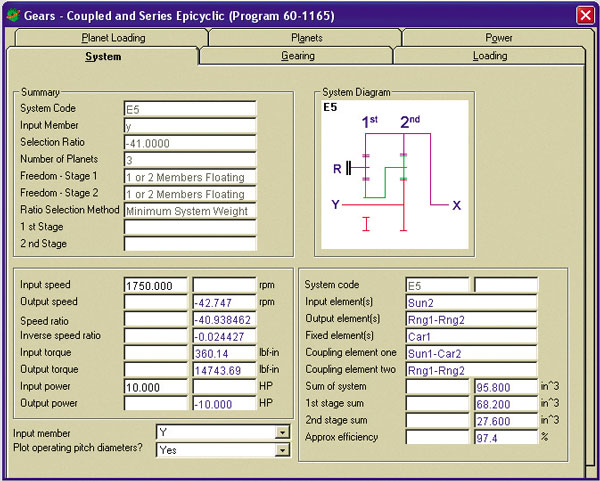
In the “split-power” coupled set shown in Figure 7, 85 percent of the transmitted power flows to ring gear #1 and 15 percent to ring gear #2. The result is that this coupled gear set can be smaller than series coupled sets because the power is split between the two elements. When coupling epicyclic sets in a series, 0 percent of the power will be transmitted through each set (see Figure 7).
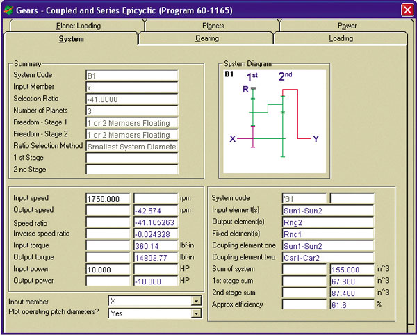
Our next example depicts a set with “power recirculation.” This gear set comes about when torque gets locked in the system in a manner similar to what happens in a “four-square” test procedure for vehicle drive axles. With the torque locked in the system, the horsepower at each mesh within the loop increases as speed increases. Consequently, this set will experience much higher power losses at each mesh, resulting in significantly lower unit efficiency (see Figure 8).
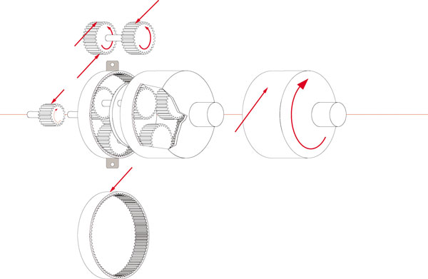
Figure 9 depicts a free-body diagram of an epicyclic arrangement that experiences power recirculation. A cursory analysis of this free-body diagram explains the 60 percent efficiency of the recirculating set shown in Figure 8. Since the planets are rigidly coupled together, the summation of forces on the two gears must equal zero. The force at the sun gear mesh results from the torque input to the sun gear. The force at the second ring gear mesh results from the output torque on the ring gear. The ratio being 41.1:1, output torque is 41.1 times input torque. Adjusting for a pitch radius difference of, say, 3:1, the force on the second planet will be approximately 14 times the force on the first planet at the sun gear mesh. Therefore, for the summation of forces to equate to zero, the tangential load at the first ring gear must be approximately 13 times the tangential load at the sun gear. If we assume the pitch line velocities to be the same at the sun mesh and ring mesh, the power loss at the ring mesh will be approximately 13 times higher than the power loss at the sun mesh (see Figure 9).
Additional Considerations
As carrier speeds increase, centrifugal forces on the planet gears become more and more significant; especially if they have a relatively large mass. These forces must be resolved by the planet bearing and oftentimes they are higher than the forces that transmit torque to the carrier. They must be considered in the planet bearing calculations.
Lubrication of the planet bearings can be challenging, especially at higher carrier speeds. These challenges have led to many highly creative solutions. Researching patents on this subject will prove beneficial. Retention of planet pins in heavily loaded sets can also prove quite challenging. Deflections will loosen press fits and crack welds. Loose fits may “wallow” out the bores in the carrier, causing more than desired float. Again, researching patents will be fruitful.
A final check that must be made—especially in high ratio planetaries—is tip clearance between adjacent planets. The time to find this answer is at the design stage… not when it adds a complication at assembly.

Dos and Don’ts
Now that we’ve looked at epicyclic gear types and arrangements and their unique design characteristics, as well as several examples, let’s discuss the dos and don’ts of epicyclic gear design.
Do:
• Calculate planet locations
• Define assembly match marks on drawing
• Address relative speeds
• Divide torques correctly
• Analyze planets as idlers in simple epicyclic sets
• Check planets for OD interference
• Use free-body diagrams
Don’t:
• Rigidly fix all members unless the application requires it
• Assume power splits
• Use coupled sets that have internal power recirculation
• Forget centrifugal loads on planet bearings

Design Tips and Pitfalls
In closing, here are some design tips to embrace and pitfalls to avoid as you design epicyclic gears. Remember that designing on standard centers will result in higher specific sliding and lower efficiency. If struggling with meshes, removing one tooth from the planet gear will enhance both sun and ring meshes. Be sure and allow “float” or specify very tight location and run-out tolerances or load sharing will be less than anticipated. Finally, use tangential loads and pitch-line velocities to determine mesh power transmission and losses.

Like any skill, designing epicyclic gears is something that becomes easier with practice. As retiring engineers take their know-how with them, younger engineers remain to pick up where they left off. Although this short primer cannot possibly cover every nuance of epicyclic gearing, hopefully it will serve as a jumping-off point for engineers tasked with designing their first epicyclic gear set—and perhaps even act as an occasional refresher for the more experienced designer.
Methodology
The UTS Integrated Gear Software (IGS) was used to perform the calculations shown in Figure 7 and Figure 8. IGS is a comprehensive gear knowledge system that helps designers optimize their designs, eliminate noise and premature failure, lower design and production costs, and shorten time to market. See ANSI/AGMA 6023-A-88 or ASME Paper 68-MECH-45 by P.W. Jensen for more information about epicyclic gears.


