


 This paper deals with gearings that operate (a) on intersected shafts and (b) on crossed shafts. The gearings that operate on intersected shafts are referred to as “intersected-axes gearings,” or just “Ia−gearings” for simplicity. Similarly, the gearings that operate on crossed shafts are referred to as “crossed-axes gearings,” also referred to as “Ca−gearings1.” Hypoid, spiroid, and a few other gear systems are covered by the terms “crossed-axes gearings.”
Introduction
The main goal of the paper is to show how the ANSI/AGMA/ISO standards for bevel and hypoid gearing; that is, [1], [2], [3], [4], and others can be benefited by the latest achievements in the theory of gearing2 [5]. All the standards, including but not limited to ANSI/AGMA/ISO standards, must provide a user with a complete and consistent information on the subject. Often, unfortunately, this is not observed.
As an example, the principal features of the determination and inspection of the design parameters of a gear and a mating pinion that directly affect the gear mesh efficiency are considered in this paper. In particular: (a) the geometrical dimensioning and tolerancing; (b) the contact pattern; (c) the mounting distance, and (d) the backlash in Ia−gearing, as well as in Ca−gearing, are discussed as examples.
As is well known, the “kinematics” and the “geometry” of a gear and a mating pinion tooth flanks are investigated in the theory of gearing. Therefore, only the kinematics of a gear pair and the geometry of the gear and the mating pinion tooth flanks are covered in this paper. However, it should be noted that use of the approach developed in the theory of gearing enables one to solve numerous problems in the field of gear dynamics, transmitted power density, noise excitation and vibration generation in a gear pair, calculating of the tolerances for the design parameters of a gear pair, and so forth.
It is shown that the theory of gearing could be a powerful tool to improve ANSI/AGMA/ISO standards [1], [2], [3], [4], and others. Some inconsistencies in ANSI/AGMA/ISO standards are discussed as the examples. The geometrical dimensioning and tolerancing, the contact pattern, the mounting distance, and the backlash are among them. A more detailed discussion of these issues would take a far lengthier paper. It makes sense to begin the discussion on bevel and hypoid gearing with an analysis of the recommended [1], [2], [3], [4], geometrical dimensioning.
Geometrical dimensioning
The set of the geometrical dimensions recommended for bevel gearing by ANSI/AGMA/ISO standards ([1] in particular), is shown in Figure 1. All the geometrical dimensions shown in Figure 1, and those not shown here, can be subdivided into two groups; that is, the geometrical dimensions that directly affect the conditions of the gear teeth engagement, and those indirectly affected by the conditions of the gear teeth engagement. Let’s take a brief look at the terminology and geometrical dimensioning recommended by ANSI/AGMA/ISO standards ([1] in particular).

For example, the back cone and the back face are used as the datum surfaces for the specification of the back angle, A. The back cone angle, B, is specified as the apex angle of the back cone. The back cone distance, C, is specified as a distance between the back cone apex (the back cone apex physically does not exist) and the pitch cone that physically also does not exist, and so forth.
Importance (and usefulness) of the items such as the crown point, E, is at least doubtful, as this datum element of poor quality. The geometrical dimension shown in Figure 1 and labeled as M is not a mounting distance at all, as the mounting distance cannot be specified in terms of the location of point M outside of the gear tooth flank (see following section on Contact Patterning).

An alternative set of the geometrical dimensions is illustrated in Figure 2. This set of geometrical dimensions is sufficient for both the gear production as well as for the gear inspection. The gear common reference surface and the gear bore are used as the main set of datum surfaces for the gear. Similarly, the pinion common reference surface and the pinion bore are used as the main set of datum surfaces for the pinion4. All the geometrical dimensions that directly affect the condition of meshing are required to be specified with respect to the corresponding set of the main datum. The rest of the design parameters are also to be associated with the corresponding set of the main datum. Because of this, the geometrical dimensioning of a bevel gear pair in Figure 2 are advantageous over those in Figure 1.
Again, an excessive plurality of datum surfaces (and sometimes the physical absence of the datum surfaces) have to be eliminated in all possible ways. In the best-case scenario, only main sets of the datum surfaces of a gear and a mating pinion are used to specify all the geometrical dimensions of a gear, of a pinion, and of the gear pair.

Next, ANSI/AGMA/ISO standards ([1] in particular) refers to the so-called “mean section” as illustrated in Figure 3. Bevel and hypoid gearings only of poor quality can be analyzed in the mean section. Moreover, many of the design parameters — such as the (a) addendum, (b) dedendum, (c) circular pitch, (d) circular thickness, (e) clearance, (f) whole depth, (g) backlash, and (h) working depth — are considered as linear dimensions [1]. All of these design parameters are angular values in nature [5]. The common vertex of all of these angles coincides with the base cone apex of the gear (of the mating pinion) [5]. The angular design parameters (a), (b), (e), (f), and (h) are specified in a section of a gear or a pinion by a plane through the centerline. The angular design parameters (c) and (d) are specified in the pitch plane, PP, of a gear pair. Finally, the angular design parameter (g) — that is, the backlash — is specified within the pitch plane, PP, of a gear pair.
Other design parameters of a bevel/hypoid gear, such as (i) chordal addendum and (ii) chordal thickness, also need to be construed as the corresponding “angular” design parameters having the gear/pinion vertex as the common vertex [5]. It is wrong practice to try to express the design parameters of a bevel/hypoid gear in terms of “pitch circle” and “equivalent radius.” All correctly engineered bevel and hypoid gearings need being considered only in 3D space, and not in equivalent plane sections as in [5].

The design parameters of a gear pair that directly affect the conditions of meshing of the interacting tooth flanks of a gear and of a pinion. They are as follows: the shaft angle, H; the pinion offset, M; the mounting distance, N; and the pitch angle, P [5]. The actual values of the tolerances for all of these design parameters of a gear pair must be very tight. All of them have to be calculated (and not just set) in terms of permissible variation in shape, size, and configuration of the desirable contact pattern. It should be stressed here that the pitch cone angle, P, can be expressed in terms of shaft angle, H ; pinion offset, M; and gear ratio of the gear pair.
The design parameters of a gear pair that directly do not affect the conditions of meshing of the interacting tooth flanks of a gear and of a pinion. They are as follows: the face apex beyond crossing point, A; the root apex beyond crossing point, B; the crown to crossing point, D; the front crown to crossing point, E; the outside diameter, F; the pitch diameter, G; the root angle, J; the face angle of blank, K; the face width, L; and the outer cone distance, R. The tolerances for all of these design parameters of a gear pair are not as tight as for the first group of design parameters of a gear pair.
The incorrect design parameters of a gear pair. This is the “pitch apex beyond crossing point, C.” In correctly engineered Ca−gearings this distance must be of a zero value [5].
The set of the design parameters of a Ca gear pair shown in Figure 4 also can be “cleaned up” similar to that in Figure 1 and Figure 2. No numerical values for geometrical tolerances are recommended by ANSI/AGMA/ISO standards for the design parameters of a gear, a pinion, and the entire gear pair; those directly affect conditions of meshing of the gear and the pinion. The discussion on geometrical dimensioning and tolerancing of bevel and hypoid gearings is briefly summarized here:
The geometrical dimensioning of a bevel gear pair shown in Figure 1 is inconsistent as the principle of common datum surfaces is violated; that is, too many datum surfaces are used in Figure 1.
The geometrical dimensioning of that same gear pair proposed in Figure 2 strictly follows the principle of common datum surfaces — the bore and the common reference surface in a gear (as well as in a pinion) are used for the purposes of geometrical dimensioning of the gear pair.
The geometrical dimension labeled as M shown in Figure 1 is not a mounting distance at all.
It is of critical importance to stress here that the base pitch, which is a design parameter No. 1 in gearings of all types, is missed in ANSI/AGMA/ISO standards for bevel and hypoid gearing. Neither base pitch of a bevel/hypoid gear, ϕ b.g, nor base pitch of its mating pinion, ϕ b.p, nor the operating base pitch, ϕb.op, of a gear pair are specified by ANSI/AGMA/ISO standards. Equality of the angular base pitches ϕb.g = ϕb.op and ϕb.p = ϕb.op is vital for: (a) the reduction of noise excitation; (b) the reduction of vibration generation; (c) an increase of power density, and so forth [7], [8], [9], [10], [11], [12], [13]. This considerable mistake in ANSI/AGMA/ISO standards for bevel and hypoid gearing needs to be fixed (the sooner, the better).
A more detailed discussion on geometrical dimensioning and tolerancing of bevel and hypoid gearings is desirable, aiming at the elimination of all possible inconsistencies. Correct dimensioning and tolerancing is a “must” in the design and production of high quality bevel and hypoid gears.
Conclusion: In intersected-axes, as well as in crossed-axes gearings, drawings for a gear, for a mating pinion, and for a gear pair must be properly dimensioned. The principle of common reference surfaces is a must to follow when dimensioning the components of a gear pair. Out-of-date terms and corresponding dimensions must be eliminated from the drawings.
Contact pattern
Bevel and hypoid gears have to be assembled in a specific way to ensure smooth running and a favorable load distribution between gears. To attain this goal, a contact pattern between the interacting tooth flanks of a gear and a mating pinion is commonly used.
The contact pattern is a critical attribute of any and all bevel/hypoid gear design (Figure 5). Simply stated, the contact pattern is the area in which the gear teeth come in contact as they engage and disengage during their rotation. When a gear is installed in a gearbox and is powering the designated application, there are varying degrees of pressure, or load, on the gear teeth. These pressures are influenced by box deflections, bearing movement and temperature changes. When the gear teeth are subjected to these variables, the contact pattern will change. There is a general rule of thumb stating that the heavier the load, the larger the contact pattern and vice versa. For a gear to perform properly under operating load, the contact pattern must be of a certain shape and at a certain location. Typically, an ideal tooth contact pattern under load should encompass the bulk of the tooth surface while avoiding any contact with the edges of the tooth flank. So far, the contact pattern is more a “qualitative” than a “quantitative” indicator of gear pair quality.

The permissible variation in contact pattern location, orientation, and shape, can be used to calculate the tolerances for design parameters of a gear pair5. Unfortunately, in contemporary gear practice, contact pattern is a qualitative, and not quantitative, measure of the gear pair quality.
The discussion on contact pattern in bevel and hypoid gearings is briefly summarized as follows:
- The contact pattern cannot be measured similar to that (and with a corresponding accuracy) as other design parameters of a gear are measured, for example, as a bore diameter, a face width, a face angle, and so forth.
- The measurements of the contact pattern are not reliable.
- The actual misalignment in bevel/hypoid gearing cannot be expressed in terms of the actual geometry and configuration of the contact pattern.
- Efforts of the gear experts must be focused toward searching possible ways to express the bevel/hypoid gears misalignment in terms of geometry, size, and configuration of the contact pattern.
Instead of the contact pattern analysis, the teeth flank geometry along with the actual value of the mounting distance should be measured. No contact pattern analysis is necessary if a bevel/hypoid gear is machined and assembled according to the properly designed blueprint. A more detailed discussion of the contact pattern in bevel and hypoid gearings is desirable.
Conclusion: This is an out-of-date practice to use contact pattern as a tool to improve the accuracy of gears for intersected-axes, and crossed-axes gear pairs. Instead, the teeth flanks geometry, and the mounting distance have to be properly specified and inspected. These can be done on the basis of a broader application of the results the theory of gearing returns. Use of the lapping process, pairing of bevel and hypoid gears, nowadays practice for the calculation of mounting distance, and tolerance for the mounting distance, reveal the lack of knowledge in the scientific theory of gearing.
Mounting distance
Mounting distance is a vital design parameter for intersected-axes gearings (that is, for bevel gearings), as well as for crossed-axes gearings (that is, hypoid, spiroid, double-enveloping worm gearings, and so forth). The specification, inspection, and tolerancing of the mounting distance is challenging to understand by practical gear engineers as this issue is insufficiently outlined in ANSI/AGMA/ISO standards. Numerous publications on the topic [14], [15], [16], [17], and many others reveal this. At the beginning, let’s clarify what the term “mounting distance” stands for.
First, and the most critical, by means of mounting distances the location of tooth flanks in axial direction of a gear and a mating pinion are specified in relation to the centerlines in the gear housing. Apex point of a tooth flank of both, of the gear, A fg, and the pinion, Afp, must coincide either with the point of intersection of the centerlines in the gear housing (for Ia−gearings), or with the “pitch plane”/“plane of action” apex (for Ca−gearings) [5]. The pitch plane apex is commonly designated as App, and the plane of action apex is commonly designated as Apa. These two conditions can be expressed as follows: Afg ≡ App ≡ Apa and Afp ≡ App ≡ Apa
Second, the pitch cone apex of a gear, Ag, (and of a mating pinion, Ap) must coincide with the apex point of a tooth flank of both, of the gear, Afg, and the pinion, Afp. These two conditions can be expressed as follows: A g ≡ A fg and Ap ≡ A fp
Third, the base cone apex of a gear, Abg, (and of a mating pinion, A bp) must coincide with the apex point of a tooth flank of both, of the gear, Afg, and the pinion, Afp. These two conditions can be expressed as follows: Abg ≡ A fg and Abp ≡ A fp.
Fourth, there are two outer cones. One of them is for the gear and another one is for the mating pinion. There are also two root cones. Again, one of them is for the gear and another one is for the mating pinion. Neither outer cones nor root cones directly affect the actual value of the mounting distance. However, these cones need to be mentioned here as in current practice outer cones are commonly used when determining the mounting distance.
In a precision gear pair, it is recommended to inspect the mounting distance at nominal operating load and the preloaded bearings.
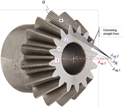
The plurality of the apexes is confusing and results in misunderstanding of the terms “mounting distance” in acting ANSI/AGMA/ISO standards. To make things clear, it is necessary to outline to the best possible extent what the term “mounting distance” stands for. As an example, consider tooth flank of a straight bevel gear6 as illustrated in Figure 6. The tooth flank of the gear, G, can be construed as a family of straight lines through each point of the gear tooth profile and the gear tooth flank apex, Afg (the gear tooth flank apex, Afg, is an equivalent to the gear base cone apex, A bg). Only the gear tooth flank apex, Afg, should be used for the specification and inspection of the mounting distance, M. Commonly, the outer cone apex of the gear, Aog.1, is inward in relation to the gear tooth flank apex, Afg, as shown for the straight generating line 1 in Figure 6. However, this is not a must as the gear outer cone apex, Aog.2, can be located either outward, or the gear outer cone apex, Aog.3, can be located inward in relation to the apex Aog.1, as it is illustrated in Figure 6 for the straight generating lines 2 and 3 of the outer cone of the gear. The actual location of the gear outer cone apex (either Aog.1, or Aog.2, or Aog.3) does not affect the conditions of meshing of the gear, G, and the pinion, P, tooth flanks. The conditions of meshing of the gear, G, and the pinion, P, tooth flanks depend only of the actual location of the gear/pinion tooth flanks apex, Afg. Therefore, the tolerance for the mounting distance (the mounting distance is measured in relation to the gear tooth flank apex, Afg) is tight, while the configuration of the apex of the outer cone of the gear, Aog, is a free dimension with no specified tolerance.

Depending on the accuracy of the set up parameters when cutting straight bevel gears, the axial position of the tooth flank, G, can be changed. After being assembled, the gear tooth flank apex, A fg, must be coincident with the centerlines in the gearbox housing. Therefore, the mounting distance of a gear is the distance from the gear tooth flank apex, A fg, to the common reference surface of the gear. A similar definition is valid with respect to the mounting distance of a pinion. In reality, as it is recommended by ANSI/AGMA/ISO standards, the mounting distance is specified differently from the preceding.
As it is shown in Figure 2, two dimensions — that is, the crown to back, F, and the pitch cone apex to crown, R — are used to specify the mounting distance, M. The crown is used to specify both the dimensions. It is right to point out here that a crown is not a reliable datum for the inspection of the mounting distance. Taking into account that tolerance for the mounting distance is very tight, it is nonsense to use the crown for precision measurements. This is the first issue that makes the crown inappropriate datum for such an inspection.
Then, the crown is not geometrically associated with the gear tooth flank, G. An analysis of Figure 7 reveals that, depending on the accuracy of the set up parameters when machining straight bevel gears, the axial position of the tooth flank, G, and the gear tooth flank apex, Afg, can be variable.

A bevel/hypoid gear tooth flank must be correctly specified in relation to the common reference surface. For this purpose an arbitrary point, m, either within the tooth flank or within extension of this surface can be used. The tooth flank apex, A fg (Figure 6), is convenient to be used for this purpose. It is incorrect practice to use the wedge, E, and the dimension, F (Figure 7), to specify the mounting distance in bevel/hypoid gearing as shown in Figure 1.
With that said, it is the right point to proceed with a discussion of a nowadays practice to specify and inspect the mounting distance in intersected-axes, and in crossed-axes gearing. The current practice is outlined in [15] and is illustrated in Figure 8. The procedure for assembling the bevel gears in this gearbox by the measurement method is as follows [15]:

- On the housing, measure the distance from locating surface to bore centerline in both horizontal and vertical directions (HMD and VMD).
- Record the gear and pinion mounting distances (MDG and MDP);
- Measure the gear and pinion thicknesses (WG and WP).
- Assemble the gears into their subassemblies.
- Measure the length that controls gear position in each subassembly (MAG and MAP).
- Calculate the distance from shim mounting surface to crossing point for each subassembly (MDV and MDH): MDV = MD G − MG + MAG and MDH = MDP − MP + MAP correspondingly (Figure 8) [15].
- Calculate the required shim thicknesses and assemble the gearbox with shims in place.
Items No. 1 through No. 5 are correct. In the item #6, when calculating the dimension MDV, the actual, MDG actual, and not the nominal, MDG, value of the mounting distance must be entered into the equation for the calculating of MDV. Similarly, when calculating the dimension MDH, the actual, M DP actual, and not the nominal,
M D P, value of the mounting distance must be entered into the equation for the calculating of MDH.
Neither the dimension M DG, nor the dimension M D P can be measured as the gear tooth flank apex, Afg, (as well as the pinion tooth flank apex, Ap) does not physically exist. The pitch cone apexes Ag, Ap , and base cone apexes Abg, Abp, also do not exist physically. Therefore, the use of the gear tooth flank, G, (and the pinion tooth flank, P) is the only possibility to measure the dimensions M DG actual and M DP actual. For this purpose, a method for inspection of the mounting distance in bevel and hypoid gearing is proposed by the author7. The proposed method of inspection is based on use of a ball of a pre-specified diameter in a space between two neighboring teeth of a gear to be inspected. A prescribed point of contact, m, (see Figure 3) is located reasonably close to the mid of the face-width gear, and to the line of intersection of the gear tooth flank by the pitch cone. It is assumed that the rest of the gear tooth flank deviations either are zero, or are known and can be incorporated in the procedure of the calculations.
For a specified point m within a gear tooth flank the dimension M *actual is measured. The measured distance M *actual is compared with its nominal value, M *. In this way a decision can be made on whether or not the actual dimension M *actual is within the tolerance.
Item No. 7 is useless. No shimming is necessary if the gears are machined to properly calculated tolerances. It is no longer required to machine gears and pinions in sets, and gears and pinions can be assembled with no regards of the sets, that is, no gear pairing is required if the gears are machined to the correctly calculated tolerances. Therefore, if engineered properly, it is possible to manufacture all gears to the nominal mounting distance specified on the drawing with no additional cost. Under such a scenario, no pairing in bevel/hypoid gearing is required, and the gears can be engaged in a correct mesh with any bevel/hypoid pinion if both of them are correctly engineered and manufactured. Moreover, if one gear in a set fails, the entire set should not be replaced, but only the failed gear is required to be replaced.
Because of dimensional variations between parts, each gear will have a unique value for the mounting distance [16]. For the mounting distance, it is common to set a tolerance of ± 0.05 mm up to ± 0.1 mm [16]. For correctly engineered bevel and hypoid gears, the tolerance for mounting distance must not be set but, instead, it must be calculated and must be expressed in terms of the permissible variation in contact pattern location, orientation, and shape. No methods to calculate the tolerances for the mounting distance are available in the public domain. No methods to verify whether or not the actual errors for the mounting distance are within the corresponding tolerance are available in the public domain.
The discussion on mounting distance in Ia− and Ca−gearings in bevel and hypoid gearings is briefly summarized as follows:
In the current practice of bevel/hypoid gear production and application, there are no means to ensure whether or not the actual value of the mounting distance is within a specified tolerance for this dimension.
An actual geometry and configuration of the contact pattern is an evidence that the mounting distance is of a reasonable value, but no one can guarantee that the actual value of the mounting distance is not out the specified tolerance.
An incorrect mounting distance is not the only reason for a shift of the contact pattern. Even if the mounting distance is within the tolerance, an unfavorable contact pattern can be observed because of: (a) the deviations of the actual tooth flank geometry from it desirable geometry; (b) the gears are designed and cut as approximate gears (even ground bevel and hypoid gears are not perfect, that is, they are not geometrically accurate), and; (c) distortions after heat treatment (especially for a gear).
Direct measurements of the mounting distance8 are necessary. This can be done, for example, by means of laser scanning of the machined tooth flank, and creating on premise of that a CAD model of the actual tooth flanks. Comparison of two CAD models, that is, of the desirable and of the actual tooth flanks returns an exact number of the mounting distance in a machined bevel/hypoid gear. Simpler methods and means for the direct inspection of the actual mounting distance in bevel/hypoid gearings can be proposed.
No reliable methods for the calculation of the tolerances for the mounting distance in bevel/hypoid gearings are known. This particular problem needs to be addressed. A more detailed discussion on mounting distance in Ia− and Ca−gearings in bevel and hypoid gearings follows:
Conclusion: Reliable methods to inspect the mounting distance can be developed on the premise of the results derived from the theory of gearing. A correct alignment (snapping of the base/pitch cone apexes in cases of Ia−gearings, and correct configuration of the base/pitch cone apexes in cases of Ca−gearings) depends on the mounting distance of both; that is, of a gear and its mating pinion. Therefore, shimming in/out of the gear/pinion is an obsolete practice. Tolerances for the mounting distance neither of a gear, nor of its mating pinion cannot be properly calculated/inspected in the contemporary production of gears.
Backlash
Bevel and hypoid gears are designed and manufactured to provide a specific amount of backlash. That is, the space between mating gear teeth or the difference in width of the gear tooth and pinion tooth of the mating gear to let the gears mesh without binding and to provide space for a film of lubricating oil between the teeth. This prevents overheating and tooth damage. The backlash is necessary for proper operation of the gear pair.
To optimize the performance of any two bevel gears, the gears must be positioned together so that they run smoothly without binding and/or excessive backlash. In the current practice of gear production, unless otherwise specified, the minimum amount of total backlash of a pair of bevel/hypoid gears is measured at the tightest point of mesh with a dial indicator on a bevel gear testing machine. Unless otherwise specified, backlash is assumed to be normal backlash9 and cannot be measured in the plane of rotation. Backlash is necessary to achieve correct operation of the gears and varies with the size of the tooth and operating conditions. Bevel gears are cut to have a definite amount of backlash when correctly assembled together. But excessive backlash or play, if great enough, can cause a sudden impulse or shock load in starting or reversing that may cause serious tooth damage. Excessive or insufficient backlash can also result in noise, excessive wear, and damage.
Numerous inconsistencies are observed in the definition and interpretation of backlash in bevel and hypoid gearings. To avoid the above discussed inconsistencies in the definition of backlash in bevel and hypoid gearings, the backlash in bevel/hypoid gearing can be defined in the following manner.
Consider a phantom crown gear that is engaged in correct mesh with the gear. This crown gear can be referred to as a “crown gear/gear,” or simply as C Gg. The outer diameter of the crown gear is labeled as r o.pp, the inner diameter is labeled as r l.pp, and the pitch diameter is labeled as r pp. Face width, Fpp, of the crown gear is equal to Fpp = r o.pp − r l.pp. The central angle Ψ pp spans over the active portion of the crown gear, CGg. The axis of rotation of the crown gear, CGg, is labeled as Opp. Here, the subscript “pp” indicates that the parameters relate to the pitch plane, PP.

Similarly, consider a phantom crown gear that is engaged in correct mesh with the pinion. This crown gear can be referred to as a “crown gear/pinion,” or simply as CG p. The angular tooth thickness, ϕ t.p, and the angular space width, ϕ w.p, of a gear is measured within the pitch plane, PP, of the “crown gear/pinion, CGp” (not shown in Figure 9). The angular pitch of the pinion teeth is labeled as ϕ x.p(not shown in Figure 9).
The angular pitches of the gear, ϕ x.g, and the pinion, ϕ x.p, are equal; that is, the equality ϕ x.g = ϕ x.p = ϕ x. Therefore, the further designations for these angular pitches are replaced with ϕ x.
When the crown gear, CGg, and the crown gear, CGp, are engaged in mesh, they are free to turn about the O pp−axis in relation to one another through a certain angle, ϕ B. The angle, ϕ B, is referred to as the “angular backlash.” The “angular backlash, ϕ B,” can be calculated as:
ϕ B = ϕ w.g − ϕ t.p Equation 1
or as:
ϕ B = ϕ w.p − ϕ t.g Equation 2
Novel instrumentation can be developed for the direct measurement of the design parameters in a gear (ϕ t.g,ϕ w.g, and ϕ x.g) and in a pinion (ϕ t.p,ϕ w.p, and ϕ x.p). Then either Equation 1 or Equation 2 can be used for the calculation of the angular backlash, ϕ B.
In a bevel/hypoid gear pair the backlash is measured at a configuration of a gear and a pinion when “two pairs of teeth are engaged in mesh.”
The discussion on backlash in I a− and C a−gearings in bevel and hypoid gearings is briefly summarized below:
- The existing practice to set and to inspect backlash in a bevel/hypoid gear pair is inconsistent.
- The angular backlash is a reliable design parameter of a bevel/hypoid gear pair.
- The angular backlash is measured within the plane of action in a gear pair (and not perpendicular to the gear teeth as it is recommended by ANSI/AGMA/ISO standards). It makes sense to specify the angular backlash as an angle within the pitch plane at a corresponding configuration of the gear and the pinion in relation to one another, and not as an angle through which the gear (the pinion) turns about its axis as values of these two angles are different: the angle for the gear is smaller compared to that for the pinion (gear ratio).
If the backlash does not fall within the recommended limits, no corrections to the mounting distance are allowed to adjust the backlash. If possible, the tooth thickness can be corrected (reduced) by additional machining. For strength calculations, the normal backlash can be expressed in terms of the backlash in the plane of rotation.
There is a trade-off when setting an actual value of backlash: The backlash must be large enough for operating of the gear pair, and it must be small enough when reversing the rotation. With the discussed approach, the contact ratio in bevel and hypoid gearing can be accurately calculated (spiral bevel, and others).
More details on the kinematics and the geometry of intersected-axis, and in crossed-axis gearing can be found in numerous recently published papers [7], [8], [9], [10], [11], [12], [13], and others.
Conclusion: Backlash in intersected-axes, and in crossed-axes gearing is an “angular” parameter, and not a “linear” parameter. Backlash is measured within the pitch plane of the gear pair. Appropriate methods of and means for inspection of the angular backlash can be developed on the premise of the developed theory of gearing [5].
Summary
In a brief overview on the acting ANSI/AGMA/ISO standards for bevel and hypoid gearings, it is shown that the geometrical dimensioning in ANSI/AGMA/ISO standards differs from the best practice of part dimensioning and in most cases can be significantly improved. Violation of the principle of common datum surfaces is the root cause for that. An alternative geometrical dimensioning for a bevel gear pair is discussed. Base pitches of a gear, of a mating pinion, and the operating base pitches of a gear pair must be incorporated into the set of the design parameters for bevel and hypoid gearings.
Use of the contact pattern for the purpose of evaluation of bevel/hypoid gear performance is briefly discussed. It is illustrated that (a) the measurements of the contact pattern are not reliable and (b) the actual misalignment in bevel/hypoid gearing cannot be expressed in terms of the actual geometry and configuration of the contact pattern. Therefore, the efforts of gear experts must be focused toward searching possible ways to express the bevel/hypoid gears misalignment in terms of geometry, size, and configuration of the contact pattern.
It is shown that in current practice of bevel/hypoid gear production and application, there are no reliable means to ensure whether the actual value of the mounting distance is within a specified tolerance for this dimension. The commonly used design parameter referred to as the “mounting distance” is not the mounting distance at all. A method for the inspection of mounting distance in intersected-axes, and in crossed-axes gearings is necessary to be developed. Once the actual value of the mounting distance is known, and the gears are cut to the correctly calculated tolerances, then: (a) the gears no longer need to be produced in sets; (b) there is no necessity to replace the entire gear pair when one of the components of a gear pair is brakes; only the broken component can be replaced instead if the gears are correctly designed and properly manufactured; (c) no pairing is necessary, and (d) potentially, lapping process in manufacturing of precision bevel and hypoid gearings can be eliminated at all.
No reliable methods for the calculation of the tolerances for the mounting distance in bevel/hypoid gearings are known (in the public domain). This particular problem needs to be addressed.
It is demonstrated that the existing practice to set and to inspect backlash in a bevel/hypoid gear pair is inconsistent. It is proposed to use the “angular backlash” when designing bevel/hypoid gear pairs.
Ultimately, the discussed examples of inconsistencies in the acting ANSI/AGMA/ISO standards for bevel and hypoid gearings show that the latest accomplishments in the scientific theory of gearing need to be taken into account when revising the acting ANSI/AGMA/ISO standards for bevel and hypoid gearings.
Footnotes
- C a−gearings also include “worm gearings.” However, worm gearings could be a subject of a separate article.
- Per the author’s observation, the current gear industry, both, the gear practitioners, as well as the gear researchers, do not value properly the accomplishments attained in the theory of gearing. The ignorance of the output from the theory of gearing is one of the root causes of insufficient gear quality, problems with the gear inspection, too-high costs of produced precision gearings, and so forth. No one has a chance to succeed with bevel, hypoid, and worm gearing having no correct knowledge of the gear kinematics and the gear geometry. Knowledge of the theory of gearing is a must for all gear experts involved in precision gear design and manufacture.
- The similar recommendation are provided in Figure 2.7 on page 22, and in Figure 2.8 on page 23 in the recently published book by J. Klingelnberg [6].
- It is worthy to stress here that the fewer the overall number of the datum surfaces, the higher the accuracy of the part machining can be attained, and vice versa.
- In much, the contact pattern is a subjective (and not objective) parameter. Neither the dimensions and orientation, nor the tolerances for the dimensions and orientation of the contact pattern can be assigned (and be directly measured on the shop floor). The contact pattern is an insufficiently engineered parameter of quality of a gear pair. The contact pattern is not measurable; that is, it cannot be reliably measured by means that are commonly available on the shop floor. It is desired to substitute the contact pattern with another reliably measurable design parameter of a gear pair. The mounting distance is a promising candidate for that.
- This concept can be easily extended to bevel gears of any and all other types [5].
- A method for inspection of the mounting distance in bevel and hypoid gearing is a subject of a separate article.
- Important: In addition to the mounting distance, in C a−gearings, one more design parameter must be inspected. This is an angle that a gear/pinion axis of rotation forms with the centerline, ℄. A tolerance for this angle needs to be specified, and the actual deviation of the angle from required value of it needs to be inspected. An appropriate tolerance for the center distance.
- A straight line along which the so-called “normal backlash” is measured cannot be perpendicular to both, to the gear tooth flank, G, and the pinion tooth flank, P, at the same time.
References
- ANSI/AGMA 2005-D03. Design Manual for Bevel Gears, Approved November 2001, 36 pages.
- ANSI/AGMA ISO 23509-A08. Bevel and Hypoid Gear Geometry, Approved May 20, 2008, 145 pages.
- ANSI/AGMA 2008-C01. Assembling Bevel Gears, Approved November 2001, 36 pages.
- ISO 23509: 2016, Bevel and Hypoid Gear Geometry, 140 pages.
- Radzevich, S.P., Theory of Gearing: Kinematics, Geometry, and Synthesis, CRC Press, Boca Raton, Florida, 2012, 743 pages.
- Bevel Gear: Fundamentals and Applications, by Klingelnberg, J., (Editor), 1st ed., Springer Vieweg, 2016 edition (December 24, 2015), 325 pages.
- Radzevich, S.P., et al, “Preliminary Results of Testing of Low-Tooth-Count Bevel Gears of a Novel Design. Part 1,” Gear Solutions, October 2014, pp. 25-26.
- Radzevich, S.P., et al, “Preliminary Results of Testing of Low-Tooth-Count Bevel Gears of a Novel Design. Part 2,” Gear Solutions, December 2014, pp. 20-21.
- Radzevich, S.P., et al, “Preliminary Results of Testing of Low-Tooth-Count Bevel Gears of a Novel Design. Part 3,” Gear Solutions, January 2015, pp. 20-23.
- [Radzevich, S.P., “Precision Bevel Gears with Low Tooth Count,” Gear Solutions, September, 2015, pp. 33-41.
- Radzevich, S.P., Irigireddy, V.V., Precision Bevel Gears with Low Tooth Count, AGMA Technical Paper 14FTM18, American Gear Manufacturers Association, 2014, 12 pages.
- Radzevich, S.P., “Principal Design Parameters of Gearing with Non-Parallel Axes of Rotations,” Gear Solutions, August, 2014, pp. 65-73.
- Radzevich, S.P., V.V., Precision Bevel Gears with Low Tooth Count, Gear Solutions, September, 2014, pp. 33-41.
- Arvin, J.L., Mifflin, T.C., (with contribution from Cervinka, J.J.), “Spiral Bevel Gear Development: Eliminating Trial and Error with Computer Technology,” Gear Technology, January/February, 2003, pp. 34-39.
- Wasilewski, R.F., “How to Install Bevel Gears for Peak Performance,” Power Transmission Design, March 1994, pp. 51-53.
- Marsh, S., “How to Design and Install Bevel Gears for Optimum Performance: Lessons Learned,” Gear Technology, June/July 2013, pp. 60-69.
- “Bevel Gear Mounting – Ask the Expert,” Gear Technology, www.geartechnology.com/questions/bevel_gear_mounting.php, 8/13/2015.


