


The custom nature of gears and the high cost of cutting tools have continued to put pressure on manufacturers to reduce the cost of gear machining quickly and with minimal disruption on the production floor. To make timely improvements without costly capital expense, more and more companies are looking to squeeze additional productivity out of existing equipment. However, improvement usually comes at a cost of interruption of production processes to allow for trial-and-error implementations. Virtual machining using finite element gear cutting simulation may help alleviate these problems and lead to finding solutions faster than conventional trial and error testing.
With finite element simulation of gear cutting, engineers can investigate results and understand how process or tooling changes affect the temperature, chip shape, and stresses during the cutting process. This data enables more informed decisions and offers the ability to test a wide range of ideas prior to investing in new cutters or making process changes on the floor. For example, instead of guessing why a cutter fractured, virtual machining simulation allows users to simulate their process conditions to see the areas of high stress and high temperature which indicate tool failure.
In 2017, Third Wave Systems released AdvantEdge Gear Machining for simulating the gear-cutting process. Previously the capabilities of the software package have focused on modeling traditional metal cutting for milling, turning, and drilling processes. It is used globally to better understand the metal cutting process and test changes in a virtual environment. Users reduce time to solution, limit machine downtime, and lower prototyping costs.
The counterpart to AdvantEdge, an NC optimization software package, Production Module, focuses on full toolpath optimization for milling and turning machining processes used in the initial turning of gear blanks and finishing of gear components.
The machining industry and current customers have been asking about gear machining in AdvantEdge for many years. Modeling requests included understanding chip evacuation, tool life, and the effect of machining on the workpiece surface material. With a combination of internal investment and funding from a NAVAIR SBIR program award, Third Wave Systems developed AdvantEdge Gear Machining, which can simulate cylindrical gear hobbing and spiral bevel gear tooth cutting for ring gears. Both face-milling and face-hobbing methods can be modeled.

Unlike general-purpose finite element software, this package is specifically designed to be used by engineers with a wide variety of backgrounds, not finite element alone. Features such as automated calculation of meshing parameters and the results analysis wizard enable new finite-element users to get to a solution more quickly without sacrificing the manual inputs and functionality an experienced user requires.
Due to the complexity of gear cutting and wide range of potential users, an industry focus group was formed including cutting tool, machine tool, and gear manufacturers. This enabled improvement of the user experience and a streamlining of inputs to the simulation with the software handling the other necessary calculations in the background.

With the help of its industry partners, Third Wave Systems has been able to create a simulation package that contains separate processes specific to cylindrical hobbing, face milling, and face hobbing. This includes inputs for defining the uncut gear blank, the tool, process parameters, and materials along with advanced setup features for manual mesh definition for experienced users. The simulation captures the custom nature of the gear tooling through use of a CAD solid model import. With the advent of digital manufacturing, a solid model may also be imported from scanned cutters found on production equipment. The ability to use both scanned and CAD-generated solid models allows for high fidelity simulation of the true manufacturing environment.
The process parameters are specific to the process type and can be found directly from the dimension sheet. The simulation allows users to set up the simulation at the beginning, middle, or end of the cutting process, capturing the specific area of interest for the engineer. This enables a user to study a single rotation of the cutting tool or single cutting tooth pattern in high detail while still receiving a solution in a reasonable amount of time.

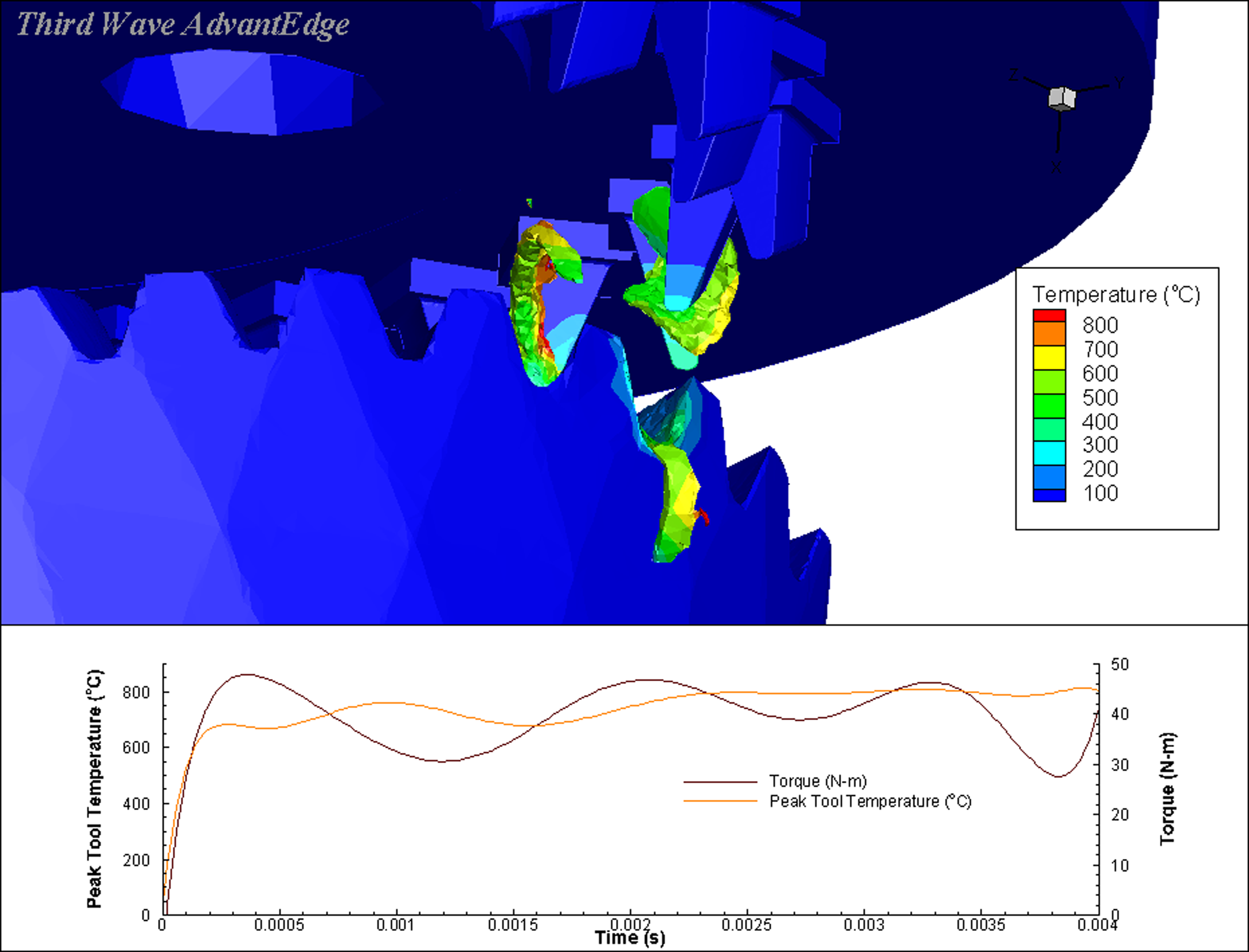
Simulation results can quickly be compared using the analysis tools included with AdvantEdge. The quick analysis window gives the user control to analyze specific variables on the tool, chip or workpiece contour plots and investigate global force, torque, and maximum tool temperature time histories. A results-analysis wizard and report-generation capability enables users to create a detailed simulation report to be distributed to co-workers, management, and customers.
The materials library for this software system includes standard materials for both the cutter and gear. The cutter can be modeled with different grades of carbide or HSS. The large standard material library available includes common gear materials AISI 1020, 1045, 4140, and 9310. These materials have been specifically created for the high strains, strain rates, and temperatures that occur during machining. A rigorous process is used for adding materials to the database that includes force validation and chip-shape collection. New materials are frequently added through TWS material modeling service.
Capturing the Process
After the user completes the initial setup of the simulation, the software takes over. Using the input parameters and imported cutter, the initial geometry setup is created. First, the gear blank is generated and cutter correctly positioned. The gear blank and tool are then rotated and a Boolean process is applied to create an in-cut gear geometry. This allows the user to start simulation anywhere during the gear-cutting process. Meshing of the gear and cutter is applied automatically followed by boundary conditions completing the setup process.

The motion of the cutter and gear are defined by the specific process kinematics. Cylindrical hobbing includes both conventional and climb cutting. For spiral bevel gear machining this includes face milling and face hobbing for the non-generating motion. Further study continues for representing the spiral bevel gear machining generating process.
To ensure the accuracy of both the initial workpiece geometry and kinematics, initial validation was conducted by the company using a Mori-Seiki NH6300 DCG 5-axis horizontal machining center. The testing setup included a Kistler 9255B table mounted dynamometer for measuring forces and chip collector for comparing chip shapes. Some simplifications were made due to the limitations of the machining center and to ensure high quality data collection. Both cylindrical hobbing and spiral bevel gear machining processes were tested using case-hardening steel material from a project partner. Chip load and speed were varied over a wide range to cover common industry practices. Concurrently with the experimental testing, simulations were set up and run for comparison. The simulated forces were found to accurately predict trends, and magnitudes were on average within 20 percent of experiment for both cutting and thrust forces. The chips were qualitatively analyzed and matched for both shape and size between simulation and experiment.

“The advanced ability to model the complex cutting process needed for hobbing cylindrical gears and cutting spiral bevel gears has the potential to reduce the cutting cycle time and improve the tool life, which will lower the cost to manufacture all gears,” said Jack Masseth, director of Gear Design and Technology at Meritor. “This extension to Third Wave System’s proven capabilities takes the gear-machining process to the next level.”
The Next Level
With the complexity of gear manufacturing, the software company is continuing to expand the number and type of processes that can be simulated. The current focus is on the automotive industry and companies with smaller diameter gears. For the larger size gears and cutters, TWS applications engineering group may be able to solve the problem through service work, but there are still some improvements necessary to release software for larger gears. Continued work with industry partners enables TWS to better understand requirements and priorities for future development for additional software features including simulation of the generating process in spiral bevel gear machining, adding more gear specific materials and expanding the size range we can simulate.


