


A brief historical overview on “Novikov gearing” is presented in this paper. It is shown that Novikov gearing is a reduced case of involute gearing. The concept of the “boundary Novikov circle” (identified by this author, and referred to as the “N – circle” for simplicity) enables a clear analysis of the geometry and kinematics of Novikov gearing. Necessary and sufficient conditions for perfect operation of the conformal gearing (that is, Novikov gearing) and “high-conformal gearing” are outlined. Use of the concept of “reversibly-enveloping surfaces” (or just “Re –surfaces”, for simplicity) makes it possible to state that gears neither Novikov gearing nor (more generally) for “high-conformal gearing” can be finish-machined in continuously indexing machining process; that is, the gears cannot be finish-cut by hobs, by shapers and rack-cutters, or by worm grinding wheel, and so forth.
Introduction
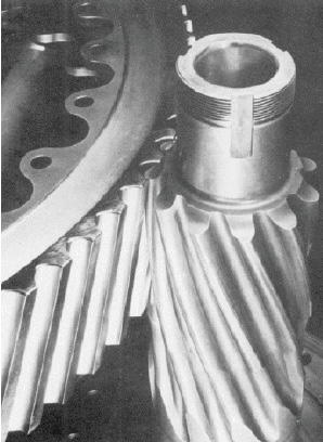
Invented at the beginning of 1950, Novikov gearing has been extensively investigated by many scientists and engineers. There is a large body of published scientific work on Novikov gearing available in the public domain. The gearing is successfully used in helicopter transmissions1 (Figure 1) [1], [2], as well as other applications.
Unfortunately, even to date the kinematics and geometry of Novikov gearing is not understood by most gear experts around the world. Many scientists and researchers in the field of gearing still loosely refer to Novikov gearing as to “Wildhaber-Novikov gearing,” or just to “W-N gearing.” This indicates insufficient training in the theory of gearing, especially the absence of understanding the kinematics and geometry of both, of Novikov gearing, and “Wildhaber gearing” as well. In this paper, the difference between two gear systems is clearly outlined. It is shown that Novikov gearing and Wildhaber gearing must be considered only separately, and it is a mistake combining two gear systems in a common system (that is, to “W-N gearing”). Potential improvements to Novikov gearing are disclosed.
1. Historical Overview
Transmission and transformation of motion is the main purpose of gearing of all kinds. The axes of rotation of the driving and the driven gears can be arbitrarily oriented in relation to one another. From this perspective, three kinds of gearing are commonly distinguished:
- parallel-axes gearing (or Pa – gearing, for simplicity),
- intersected-axes gearing (or Ia – gearing), and
- crossed-axes gearing (or Ca – gearing).
For simplicity, but without loss of generality, the consideration below is limited only to Pa – gearing.
In the past, pin gearing, as well as other primitive kinds of gearing, were in use. None of them is capable of transmitting a rotation smoothly. Swiss mathematician and mechanician Leonhard Euler2 proposed involute gearing — the only kind of Pa – gearing that is capable of transmitting smoothly a steady rotation from a driving shaft to a driven shaft. Gearing of no other kind is capable of doing that. The required equality of the base pitches can be observed in involute gearing only and not in other gear systems.
In external involute Pa – gearing, a convex involute tooth profile of the driving member contacts a convex involute tooth profile of the driven member. In other words, external involute Pa – gearing features “convex-to-convex contact” of the mating tooth profiles. As the contacting tooth profiles are convex, this imposes a strong limitation on the bearing capacity of the involute gearing because of high contact stress in “convex-to-convex contact”. It is highly desired to replace two convex contacting tooth profiles of the gear teeth with their “convex-to-concave contact.” In conventional involute gearing this is not permissible, as it inevitably entails the violation of three fundamental laws of gearing [3].
The breakthrough invention in the realm of gearing has been made in 1950. As early as 19563, a novel gearing was proposed by Dr. M. Novikov [4]. The concept of the proposed gear system is illustrated in Figure 2 [4]. Later on, Novikov gearing was investigated in his doctoral thesis [5] and are summarized in the monograph [6].
Below, we do not follow the approach used by Novikov to design a gear pair of novel design. Instead, the concept of Novikov gearing is derived on the basis of conventional external parallel-axes involute gearing. Gearing of this kind is chosen for the derivation, as in nature Novikov gearing is a reduced case of involute gearing2.
2. Principal Design Features of Novikov Gearing
For the designing a pair of Novikov gearing, let’s assume that a location and orientation of the axes of rotation of the driving, and driven members of the gear pair to be designed is specified, and the gear ratio is given. The desired value of the transverse pressure angle is also known. With that said, a pair of Novikov gears can be designed following the routine briefly outlined below.
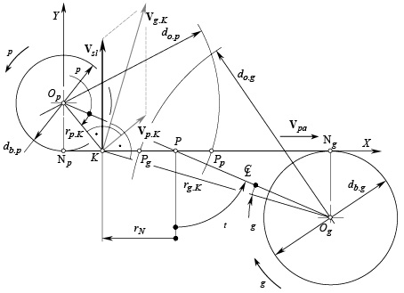
2.1. Vector diagram of a gear pair. Designing a pair of Novikov gears begins with the construction of the vector diagram of the gear pair to be designed. The rotation vector4 of the gear, ωg, is along the axis of rotation, Og, of the gear. The magnitude, ωg, of the rotation vector, ωg, equals to ωg = | ωg |. The rotation vector of the mating pinion, ωp, is along the axis of rotation, Op, of the pinion. The magnitude, ωp, of the rotation vector, ωp, is ωp = | ωp |. The magnitudes, ωg and ωp, relate to one another as: u = ωp / ωg.
The axes of rotation, Og and Op, are at a certain center-distance, C. The rotation vectors, ωg and ωp, form a crossed-axes angle, Σ, that is: Σ = ∠(ωg; ωp). In a case of external Pa – gearing, the angle, Σ, always equals Σ = Σ 180º; in internal Pa – gearing the equality Σ = 0º is valid.
The principle of inversion of rotations can be implemented to the gear pair to be designed. Let’s assume that both the axes of the rotations, Og and Op, are rotated together with the rotation vector, –ωg. Because the identity ωg + (–ωp) ≡ 0 is valid, the gear becomes stationary under the additional rotation, –ωg. The pinion is rotated with the rotation: ωpl = (ωp – ωg). The vector of instant rotation, ωpl, of the pinion in relation to the gear is along the axis of instant rotation, Pln. More in detail the vector diagrams are discussed in [3].
2.2. Plane of action in parallel-axes gearing. The plane of action, PA, in parallel-axes gearing is a plane through the axis of instant rotation, Pln. This plane forms a transverse pressure angle, φt, with the perpendicular to the plane through the axes of rotation, Og and Op, of the gear and of the pinion respectively. The base diameter of the gear, db.g, and that of the pinion, db.p, can be expressed in terms of the pitch radii, rg and rp, of the pitch cylinders, and the transverse pressure angle, φt:
db.g = 2rg cos φt Equation 1
db.p = 2rp cos φt Equation 2
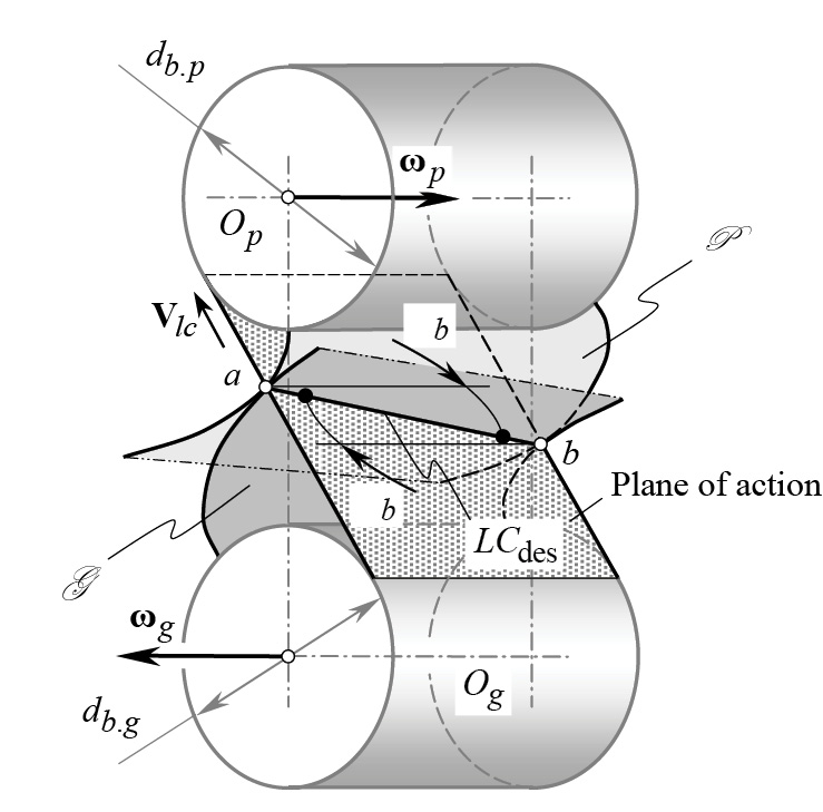
Once the base cylinders are determined, then transmission of a rotation from the driving member to the driven member of the gear pair can be interpreted with the help of the so-called “pulley-and-belt analogy” (Figure 3).
Either equation (1) or (2) can be used for the derivation of an expression for the calculation of the base pitch, pb, in a transverse section of the gear pair:
pb = π db.g / Ng = π db.p / Np Equation 3
Equation (3) is valid for Pa – gearing that is capable of transmitting a rotation smoothly.
2.3. A desired line of contact in parallel-axes gearing. The tooth flank of the gear, G , and that of the pinion, P , make contact along a desired line of contact, LCdes (Figure 3) or just a line of contact, LC. The line of contact, LC, is a planar curve of a favorable geometry that is entirely located within the plane of action, PA. The teeth flanks, G and P of the gear and the mating pinion interact only within the active portion of the plane of action, as is shown in Figure 4.
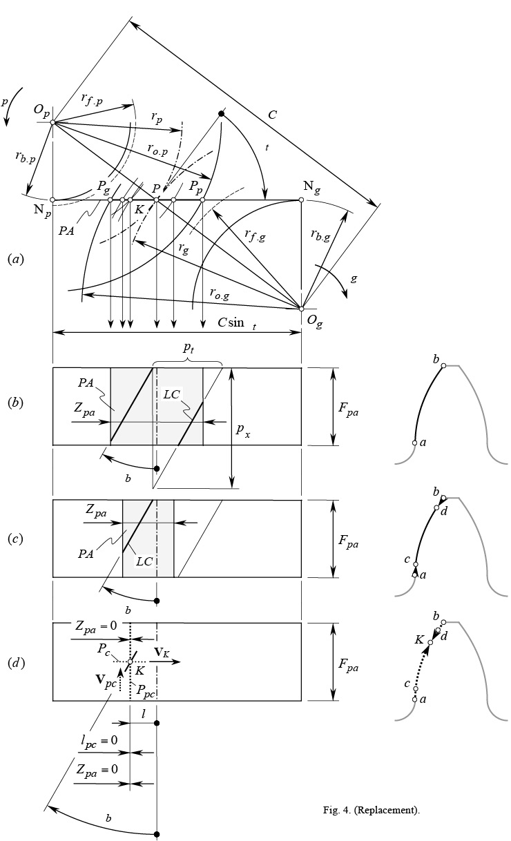
Referred to %%0218-Rad-4%%a, the straight-line segment, NgNp, is the total length of the plane of action. In reality, the active portion of the plane of action, PA, is of a shorter length, Zpa (%%0218-Rad-4%%b). In a case of Novikov gearing, the equality, Zpa = 0, is observed.
In involute helical Pa – gearing, the desired line of contact, LC, between the tooth flank of the gear G and the pinion P (remember, that the tooth flanks, G and P , are not constructed yet) is a straight-line segment that forms a base helix angle, Ψb, with the axis of instant rotation, Pln.
The total contact ratio, mt, can be expressed in terms of the transverse contact ratio, mp, and the face contact ratio, mF:
mt = mp + mF Equation 4
where: mp = Zpa /pb and mF = Fpa tanΨb /pb.
The inequality, mt ≥ 0, must be observed for any and all parallel-axes gear pairs.
When the base cylinders of diameters, db.g and db.p, rotate, the desired line of contact, LC, travels (together with the plane of action, PA) in relation to the reference systems, one of which is associated with the gear and another associated with the pinion. In such a motion, the tooth flank of the gear, G (as well as the tooth flank of the pinion, P ) can be interpreted as a family of consecutive positions of the desired line of contact in the corresponding reference system.
In the example (Figure 4b), the active portion, ab, of the gear tooth profile5 is shaped in the form of an involute of a circle. The profile, ab, is specified by the radii of the outer cylinders of the gear and of the pinion, ro.g and ro.p , correspondingly. Point a corresponds to the “start-of-active-profile” point (SAP – point), while point b corresponds to the “end-of-active-profile” point (EAP – point).
For both members of a gear pair — that is, for the gear and the pinion — the radius, reap, of the EAP – circle can be smaller than the outer radius of the gear, ro.g (or than the outer radius of the pinion, ro.p , for example) due to chamfering. Under such a scenario (Figure 4c), the active portion of the plane of action gets narrower. The SAP – point c, and the EAP – point d become closer to one another: The active portion, cd, of the involute tooth profile is shorter than that, ab, illustrated in Figure 4b. This gives a certain freedom to the gear designer when selecting the geometry of non-active portions, ac and bd, of the tooth profile. As these portions of the tooth profile do not interact with one another, the geometry of the segments, ac and bd, is not restricted by the conditions of meshing of the tooth profiles (which is the must for the active portion, cd).
In the extreme case, the EAP – circles of the gear and of the pinion can pass through a certain point K within the straight-line segment, PgPp. Because of this, the length, Zpa, of the active portion of the plane of action becomes zero (Zpa = 0), and the active portion of the involute tooth profile shrinks to point, K. This point is referred to as the “involute tooth point.” The non-active portions, aK and bK, of the tooth profile meet each other at point, K. These portions are not subject to conditions of meshing of tooth profiles, thus this gives a certain freedom to the gear designer when selecting the geometry of non-active portions, aK and bK, of the tooth profile (Figure 4d).
As the length of the active portion of the plane of action is zero (Zpa = 0), and the involute tooth profile is shrunk to point, the transverse contact ratio, mp, results in a zero value. In order to meet the inequality, mt ≥ 0, the following inequality must be met:
mt = mp + mF = 0 + mF = mF > 0 Equation 5
The point system of Pa – gearing (Figure 4d) gives much freedom when designing non-active portions of tooth profiles of the gear and the pinion as the geometry of these portions is free of constraints imposed by conditions of the meshing of two conjugate tooth profiles.
2.4. Design features of Novikov gearing. The concept of Novikov gearing is based on the schematic depicted in Figure 4d. For this case, Novikov proposed to replace “convex-to-convex contact” of the teeth profiles in involute gearing with their “convex-to-concave contact” in Novikov gearing. The replacement only becomes possible in a case when the active portion of the involute tooth profile is shrunk to point (and it is infeasible in cases when the active portion of the involute tooth profile is of a certain length [3]).
Shown in Figure 2, the first (in time) schematic that illustrates the concept of Novikov gearing [4] is far from being the best and most consistent.
Point of contact, K, of the tooth flanks, G and P , is located within the straight line of action, LA. The larger the distance of the contact point, K, from the pitch point, P, the more freedom is there for the gear designer in selecting the radii of curvature of the interacting tooth profiles. At the same time, the larger the distance of the contact point, K, from the pitch point, P, the higher losses on friction between the tooth flanks, G and P , and the higher the tooth flanks wear (Figure 5). Ultimately, the actual location of the contact point, K, is a tradeoff between the two factors just mentioned.
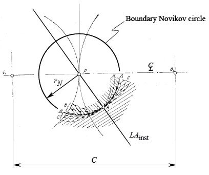
Further, let’s assume that the pinion is stationary, and the gear performs an instant rotation in relation to the pinion. The axis, Pln, of the instant rotation, ωpl, is a straight line through the pitch point, P. When the pinion is motionless, the contact point, K, traces a boundary Novikov circle6 of a radius, rN, that is centered at P, as illustrated in %%0218-Rad-2%%.
The pinion tooth profile, P , can either align with a circular-arc of the boundary Novikov circle of a radius, rN, or it can be relieved in the bodily side of the pinion tooth. The pitch point is included into the interval, while the contact point, K, is not. From the other hand, the location of the center of curvature of the concave gear tooth profile, G , within the straight line, LA, is limited to the open interval P ➞ ∞. Theoretically, the pitch point, P, can be included in this interval for K. The radius of curvature, rp, of the convex the pinion tooth profile, P , is smaller than that, rg, of the concave the gear tooth profile, G. Thus, the inequality rp < rg is observed7.
In Novikov gearing, both the pinion, and the gear are helical. The helices are of the opposite hand. No spur Novikov gearing is feasible at all. Due to that, when the gears rotate, contact point, K, “pseudo-travels” axially parallel to the axis of instant rotation, Ppl. In this straight “pseudo-motion,” the contact point traces a straight line, Ppc, that is called the “pseudo-path of contact, Ppc” [as the equality Zpa = 0 is observed, the length of the path of contact, Pc, at every transverse section is always zero (Pc ≡ 0)].
The radial position of the contact point, K, on both the gear and pinion teeth flanks, G and P , remains the same. It is, therefore, fundamental to the operation of the gears that contact occurs nominally at a point, the path of contact is of a zero length (Pc ≡ 0), and that the point of contact pseudo-travels axially across the full face width of the gears during rotation. The pseudo-travel distance is equal to Ppc = Fpa. It should be stated as a condition of the operation of Novikov gearing that, for a given profile, the tooth surfaces should not interact before or after culmination when rotated at angular speeds that are in the gear ratio.
The transverses contact ratio, mp in Novikov gearing is zero, (mp = 0). Because of this, geometrically, the meshing of the gear teeth in transverse section is instant. The face contact ratio, mF, of the gear pair is always greater than one (mF = mt > 1).
2.5. Principal design parameters of Novikov gearing. From a historical perspective, it is interesting to consider the calculation of the principal design parameters of a Novikov gear pair following the approach proposed by Novikov [6]. In current terminology and designations, the calculation of the principal design parameters of a Novikov gear pair is considered in [3].
3. High-Conformal Gearing
Conditions under which “convex-to-concave contact” between the tooth flanks of a gear and a mating pinion becomes feasible is the fundamental achievement by Novikov. Once the active tooth profiles in a parallel-axes involute gearing shrunk to a point (that is, to the “involute tooth point”), then a favorable contact between the tooth flanks, G and P , can be attained. A capability to accommodate for the manufacturing errors and for the displacements under an operating load is the only consideration when determining the geometry of the interacting tooth profiles, G and P, by Novikov.
3.1. A critical degree of conformity in Novikov gearing. It was assumed from the very beginning that convex-to-concave contact between the tooth flanks of a gear and a mating pinion is sufficient for a significant increase of bearing capacity of the contact area between the tooth flanks, G and P. The analysis reveals that in case of Novikov gearing, convex-to-concave contact is necessary, but not sufficient for a significant increase of power capacity of Pa – gearing. A certain critical degree of conformity at point of contact, K, of the tooth flanks, G and P , must be attained in order to make the convex-to-concave contact beneficial. An increase in the degree of conformity under its critical value — that is, from δacnf to δbcnf — makes possible a limited increase of the bearing capacity of the gear pair. A low increase of the bearing capacity is because of both the values of degree of conformity (that is, δacnf and δbcnf ) are smaller the critical its value [δcnf], and thus the inequalities δacnf < [δcnf] and δbcnf < [δcnf] are observed.
However, when the actual degree of conformity, δccnf, becomes larger than the critical value (δccnf > [δcnf]), then even a small increase in degree of conformity at the point of contact of the tooth flanks, G and P, causes a significant increase in bearing capacity of the tooth flanks in Novikov gearing. Therefore, the substitution of convex-to-convex contact between the tooth flanks in Pa – gearing with their convex-to-concave contact (as in Novikov gearing) is necessary, but not sufficient for a significant increase in power capacity of a parallel-axes gear pair. In addition to that, a certain critical degree of conformity, [δcnf], at point of contact between the tooth flanks of the gear, G and of the pinion P , must be exceeded.
Gearing for which degree of conformity, δcnf, at point of contact of the tooth flanks, G and P, is larger than its critical value, [δcnf] — that is, the gearing for which the inequality, δcnf > [δc ], is observed — is referred to as the “high-conformal gearing.”
The intuitively understood qualitative term “degree of conformity” can be quantified. For this purpose, a characteristic curve called the “indicatrix of conformity, CnfR (G /P )”, at the point of contact of the tooth flanks of a gear, G, and a mating pinion, P , is commonly used [3], [7]. The indicatrix of conformity, CnfR (G /P ), is a planar centro-symmetrical curve of the fourth order. Position vector of a point, rcnf, of the indicatrix of conformity corresponds to degree of conformity of the tooth flanks, G and P, in a corresponding direction through the contact point K [3], [7]. The smaller the radius, rcnf, the larger the degree of conformity at point of contact of the surfaces, and vice versa.
3.2. A minimum required degree of conformity at the point of contact the interacting tooth flanks. Favorable conditions of contact of the tooth flanks of the gear and the pinion is the main anticipated advantage of a high-conformal gear pair. The higher the degree of conformity, the higher the load-carrying capacity of the contacting tooth flanks. Therefore, a minimum possible mismatch in the curvature of the teeth of gear and pinion is desired.
In reality, tooth flanks of a gear and a mating pinion in a high-conformal gear pair are displaced from their desired position. The undesired displacements are mostly because of: (a) the manufacturing errors, and (b) the elastic deflections of the gear teeth, of the gear shafts, of the housing that is occurred under the applied load, thermal expansions of the components, and so forth. High-conformal gearing is sensitive towards the tooth flanks displacements.
To accommodate for the inevitable displacements, a certain degree of mismatch in the curvature of the teeth of gear and pinion is required. A small mismatch can be incapable of accommodating the displacements. However, as the mismatch increases, the contact stresses increase as well. High contact stress may lead to various forms of surface failure such as heavy wear, pitting or scuffing damage. Therefore, a minimum required degree of mismatch in the curvature of the teeth of gear and pinion is necessary to be determined. Otherwise, one of two scenarios could be observed. First, the gear pair is capable of absorbing the inevitable displacements of the tooth flanks, but the degree of conforming of the contacting tooth flanks is not sufficient for high load-carrying capacity of the gear pair. Second, the gear pair features sufficient degree of conformity of the tooth flanks, but is not capable of accommodating for the tooth flank displacements. In both cases, the gear pair has no chance being successfully used in practice.
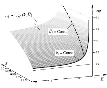
Shown in Figure 6 is a 3D plot of the function δcnf = δcnf (k, K–). %%0218-Rad-6%% relates to the cases of convex-to-concave contact of tooth flanks of the gear, G, and the pinion, P.
The performed analysis of the 3D plots allows for the following conclusions.
The sections of the surface, δcnf = δcnf (k, K–), by planes ki = Const (Figure 6) are represented with curves that have asymptotes. For a particular curve, ki = Const, shown in Figure 6 in bold line, the axis, δcnf, and the straight line, δcnf = 1, are the asymptotes.
The greatest possible degree of mismatch in the curvature of the teeth of gear and pinion corresponds to the parameter, K– ➞ ∞. The interval of alteration to the parameter, K–, starting from –∞ and going up to approximately, K– = –2, is convenient to accommodate for any desired displacement of the tooth flanks, G and P , from their correct configuration. However, within the interval (–∞ < K– < –2) of alteration in K–– parameter, an increase of the degree of conforming of the tooth profiles, G and P, is negligibly small. Within this interval of K–– parameter, the load-carrying capacity of a conformal gear pair is remained approximately at the same range. Therefore, just convex-to-concave contact between the tooth flanks of a gear and a mating pinion gives a limited improvement in the load-carrying capacity of a gear pair. Being convex-to-concave, an additional requirement needs to be satisfied in order to get not just conformal gearing, but instead to get high-conformal gearing.
On the other hand, even small change to value of the K–– parameter within the interval (–2 < K– < –1) results in significant increase of the degree of conformity of the teeth flanks, G and P. This immediately entails a corresponding increase in load-carrying capacity of the gear pair.
In the example considered above, the value of the K–– parameter (that is, the value of K– ≈ –2) can be referred to as its critical value, K–cr. This allows for distinguishing between just conformal gearing (for which –∞ < K– < K–cr) from high-conformal gearing (for which K–cr < K– < –1).
Without going into details of the analysis, it is clear that gears for high-conformal gearing require tighter tolerances for any possible displacements of the tooth flanks, G and P, from their desired location and orientation. Otherwise, there could be no future for application of high-conformal gear system.
Based on the results of the performed analysis, the following statement is valid: conformal gearing and high-conformal gearing meet all three fundamental laws of gearing [3], [7], [8]. They are capable of transmitting an input-steady rotation smoothly. As a consequence, conformal gearing, as well as high-conformal gearing, feature:
The transverse contact ratio is identical to zero (mp ≡ 0);
The total contact ratio, mt, is equal to the face contact ratio, mF, and is greater than one (mt = mF > 1);
The tooth profile of one member of the gear pair is convex, while the tooth profile of the mating gear is concave;
The convex tooth profile of one member of the gear pair is entirely located within the interior the boundary N – circle, while the concave tooth profile of another member of the gear pair is entirely located within the exterior of the boundary N –circle;
The difference between the magnitudes of radii of curvature of the concave tooth profile and the convex tooth profile in the gear pair is equal to, or smaller the given threshold beyond which higher conformity of the interacting tooth profiles contributes much to the bearing capacity of the gear pair.
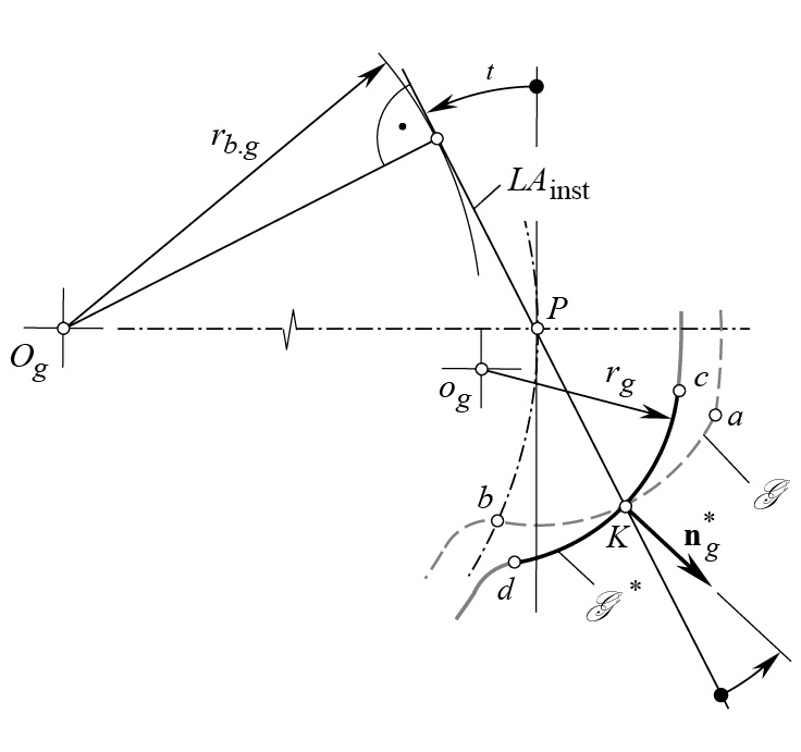
The principal difference between Novikov gearing and between Wildhaber gearing is clearly illustrated in Figure 7.
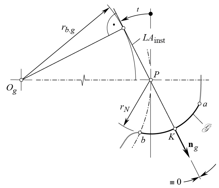
In Novikov gearing, the common unit perpendicular, ng, is always aligned with the instant line of action, LAinst, as illustrated in Figure 7a. The gear tooth flank, G, is properly configured in relation to the boundary N – circle of a radius, rN.
In Wildhaber gearing, the common unit perpendicular, ng, is not aligned with the instant line of action, LAinst, as illustrated in Figure 7b. The gear tooth flank, G* is improperly configured in relation to the boundary N – circle in a gear pair.
Helical gearing with circular-arc tooth profile proposed by Dr. E. Wildhaber [9] does not meet three fundamental laws of gearing. Insufficient understanding of gearing of this particular kind clearly follows from the paper by T. Allen [13]. The comparison of the Novikov gearing [4] and the Wildhaber gearing [9], started decades ago by N. Chironis [10], is incomplete. To the best possible extent, the comparison was later accomplished in my own work as summarized in [3], [8], [11].
Two points need to be mentioned here. First, neither gears for Novikov gearing, nor gears for high-conformal gearing, can be finish-cut by continuously-indexing method of gear machining. That is, the gears cannot be hobbed, shaped, or ground by the worm grinding wheel.
This is because three fundamental laws of gearing are not fulfilled in the gear machining mesh [7]. Only Re– surfaces can be accurately generated in a continuously-indexing method of gear machining. Cutting tools for machining gears for both — for Novikov gearing as well as for high-conformal gearing — are considered in [8] and [12].
Second, neither tooth profile nor longitudinal modification of the tooth flanks of the gear and the pinion is applicable to Novikov gearing, as well as to high-conformal gearing in a more general case.
Conclusion
It is stressed in this paper that poor understanding of the kinematics and geometry of the novel kind of gearing proposed by Novikov is the root cause for loosely combination of Novikov gearing with Wildhaber gearing. These two types of gearing must be considered only separately from one another. The terms “Wildhaber-Novikov gearing,” as well as “W-N gearing,” are incorrect, and must thus be eliminated from scientific communication on gearing.
It is a mistake to refer to Novikov gear system as to gears with a “circular-arc tooth profile.” Novikov gearing is not a kind of gearing with a circular-arc tooth profile like gears in a Wildhaber gear system. Novikov gearing is a reduced kind of involute gearing. In Novikov gearing, the working involute tooth profile is shrunk to a point. This point is referred to as the “involute tooth point.” The rest of the tooth profile is inactive, and thus can be shaped with no constraints imposed by the three fundamental laws of gearing.
The acting standards on Novikov gearing (in Russia, China, and elsewhere), and on gear cutting tools for cutting gears for Novikov gearing are generally incorrect. Gears for Novikov gearing cannot be cut (finish-cut) by hobs, shaper cutters, shavers, worm grinding wheels, and others. No generating machining of gear teeth flanks are allowed. Only disk type mill-cutters, disk form grinding wheels, and so forth, can be used for this purpose.
High-conformal gearing has a huge potential for application in high-power-density transmissions, and in low-noise gear transmissions.
References
- Shotter, B.A., “Experiences with Conformal/W-N Gearing,” Proceedings of World Congress on Gearing, Paris, France, June 22-June 24, 1977, pp. 527-540.
- Shotter, B.A., “The Lynx Transmission and Conformal Gearing,” SAE Technical Paper 781041, 1978.
- Radzevich, S.P., Theory of Gearing: Kinematics, Geometry, and Synthesis, CRC Press, Boca Raton Florida, 2012, 743 pages.
- Pat. No. 109,113, (USSR). Gearing and Cam Mechanisms Having Point System of Meshing, M.L. Novikov, National Classification 47h, 6; Filed: April 19, 1956, published in Bull. of Inventions No.10, 1957.
- Novikov, M.L., The Principles of the Geometric Theory of Point Meshing of Gearing for the Purpose of Transmitting of High Power, Doctoral Thesis, Moscow, Aviation Engineering Academy bearing the name of Prof. N.Ye. Zhukovskii, 1955.
- Novikov, M.L., Gearing that is featuring a Novel Kind of Meshing, Moscow, Published by Aviation Engineering Academy bearing the name of Prof. N.Ye. Zhukovskii, 1958, 186 pages.
- Radzevich, S.P., Geometry of Surfaces: A Practical Guide for Mechanical Engineers, Wiley, 2013, 264 pages.
- Radzevich, S.P., High-Conformal Gearing: Kinematics and Geometry, CRC Press, Boca Raton, Florida, 2015, 352p.
- Pat. No. 1,601,750, (USA). Helical Gearing. /E. Wildhaber, Filed: November 2, 1923, published October 5, 1926.
- Chironis, N., “New Tooth Shape Taking Over? Design of Novikov Gears”, pp.124-135 in: Gear Design and Application, Edited by Nicholas Chironis, McGraw-Hill Book Company, New York, 1967, 374p.
- Radzevich, S.P., Dudley’s Handbook of Practical Gear Design and Manufacture, 3rd edition, CRC Press, Boca Raton Florida, 2017, 606 pages. [Radzevich, S.P., Dudley’s Handbook of Practical Gear Design and Manufacture, 2nd edition, CRC Press, Boca Raton Florida, 2012, 880 pages].
- Radzevich, S.P., Gear Cutting Tools: Science and Engineering, 2nd Edition, CRC Press, Boca Raton Florida, 2017, 606 pages. [1st edition: Radzevich, S.P., Gear Cutting Tools: Fundamentals of Design and Computation, CRC Press, Boca Raton Florida, 2010, 786 pages.
- Allan, T., “Some Aspects of the Design and Performance of Wildhaber-Novikov Gearing,” Proc. Inst. Mech. Engrs, Part I, v. 179, n. 30, 1964/1965, pp. 931-954.
Endnotes
- These gears in Westland Helicopters. Ltd. were finish-cut by disk-grinding wheel.
- The proposed by L. Euler involute gearing deserves to be called as “Euler gearing,” or just as “gearing,” for simplicity.
- It should be mentioned here that the first pair of Novikov gears made out of an aluminum alloy (a pre-prototype) had been cut on April 25, 1954 by means of disk-type mill cutter. Fifteen gear pairs for testing purposes had been machined in summer of 1954 by means of disk-type mill cutter.
- It should be stressed here that a rotation in nature is not a vector at all. However, if special care is undertaken, rotations can be treated as vectors.
- The tooth involute profile is called “involute” because the active portion of the tooth profile is shaped in a form of an involute of a circle, regardless of the rest of the gear tooth profile (fillets, bottom-lands) are not involute.
- It is instructive to mention here that Dr. M. Novikov did not use the concept of the “boundary circle.” At the beginning of 2000s, the concept of the “boundary circle” was introduced by Dr. S. Radzevich [3]. He also proposed to refer to this circle as to the “boundary Novikov circle,” or just as to “N– circle” of a limiting radius, rN.
- It should be pointed out here that there are no constraints to design a gear pair with a convex gear tooth profile, and with a concave pinion tooth profile.
About the author: Stephen P. Radzevich, M.S., Ph.D., Dr. (Eng.) Sci., can be reached at 586-292-7209 or radzevich@usa.com.


