


A frequently asked question is "How good does the alignment have to be?" This column and the next will attempt to answer that question. In many cases, the allowable gear misalignment is less than what you might expect.
More gearboxes are being manufactured with surface-hardened and ground gears with a much higher load per square millimeter than their predecessors. Shaft, gear, bearing, and housing deflections can be higher, so initial alignment and deflections under load become more critical. And unlike softer through-hard gears, surface-hardened gears fail before they wear in.
To help explain all the issues involved we are going to look at an example. Our example is the third reduction mesh of a large industrial gearbox. It is a 15/57 tooth, 13 module, carburized, and ground gear set with a 206mm face width and manufactured to Grade A5 accuracy per AGMA 2015-1-A01. Center distance is 482mm, and both the pinion and gear shafts are supported on spherical roller bearings. The first parameters to look at are the manufacturing tolerances that affect misalignment at light load.
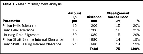
- Pinion and Gear Helix Errors: Since gears can't be made perfect, one item that has to be looked at is the misalignment due to the manufacturing errors in the gears themselves. Helix error translates directly into misalignment, and in our example set the total helix error tolerance Fb across the tooth face is +/- 15µm for the pinion and +/- 16µm for the gear.
- Housing Bore Alignment: The drawing for the housing shows a tolerance of +/- 50µm on the alignment of the centers of the housing bores from one side of the housing to the other. The bores are 680mm apart, and if we assume that the bores are out of parallel in the worst direction this would translate into +/- 15µm of misalignment across the 206mm wide face width of the gear set.
-
Bearing Radial Clearance: Unless the shaft bearings run with preload, they have some internal radial clearance and the shafts do not run centered in the bearings. This affects shaft and gear alignment. In this example, because spherical roller bearings are used and there are net thrust loads on the shafts, one bearing on each shaft would run with the inner race centered in the outer race. The type of bearing used and thrust to radial load ratio determine whether this is always the case.
The bearings in our example have normal clearance, and the unmounted internal radial clearance ranges from 110 to 170µm. The inner races are mounted with interference fits that reduce the probable mounted internal clearance to approximately 44 to 94µm. Under light load, the center of the bearing will run offset from center by half the internal clearance, or 22 to 47µm. Dividing by the distance between the bearings of 680µm yields a probable misalignment per shaft of 6.7 to 14.2µm across the face of the gears.
After you determine the magnitude of the bearing offsets in the radial direction, you need to determine the direction and how this motion affects the pinion to gear alignment perpendicular to the involutes along the line of action. The calculations can get complicated when the shafts have additional gears and loads on them, and if the shafts are not all in a line. Fortunately, there are computer programs available that perform these calculations.
Table 1 summarizes the items discussed and shows the contribution of each to the total. This allows you to see which parameter has the largest affect and what needs to be improved if the overall misalignment is too large. The next column will look at deflections under load and how–when combined with the items above–this affects operating alignment and tooth stresses.


