


In the proposed approach, the tooth flanks of the gear, G, and the pinion, P, are generated by means of a desirable line of contact, LCdes. This means that the line of contact between the tooth flanks G and P is designed before the tooth flanks themselves are designed. Use of such an approach enables the gear designer designing bevel gears featuring the line of contact with the most favorable contact geometry. For more details on the contact geometry of surfaces (that is, of the tooth flanks G and P), the interested reader is referred to [1] and other advanced sources.
In the example, the desired line of contact, LCdes, between the tooth flanks of the gear, G, and the pinion,P, is a circular arc of a radius Rlc = 200 mm (Figure 1). The arc is entirely located within the plane of action, PA. At the middle of the face width, the line of contact forms a spiral angle ψlc = 10º (not shown in Figure 1).

In a local reference system xlcylczlc associated with the plane of action,PA, and centered at the center, Olc, of the circular arc of the radius Rlc, the position vector of a point, r (lc) des, of the desired line of contact, LCdes, can be analytically described by an expression in the form:
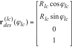
(Equation 1)
where Φlc is the angular parameter of the desired line of contact, LCdes.
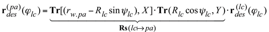
In a reference system Xpa YpaZpa (not shown in Figure 2) associated with the plane of action,PA, and centered at the apex,Apa, the position vector of a point,r (pa) des, of the desired line of contact,LCdes, can be analytically described by an equation:
(Equation 2)
where Tr[(rw.pa –Rlc sin ψlc), X] and Tr[(Rlc cos ψlc), Y] are the standard operators of the translations along the coordinate axes X and Y, correspondingly. The standard formula [1] can be used for the calculation of these operators. Rs (lc pa) is the operator of the resultant coordinate system transformation, that is, the operator of the transition from xlcylczlc to Xpa YpaZpa. rw.pa is the pitch (mid) diameter of the plane of action, and X is the shift of the reference system xlcylczlc along the X axis of the reference system Xpa YpaZpa. In other words, rw.pa and X are the coordinates of the origin Olc in the reference system Xpa YpaZpa. Ultimately, it can be shown that in the reference system Xpa YpaZpa associated with the plane of action, the position vector of a point,r (pa) des, can be rewritten in the following form:
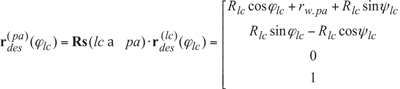
(Equation 3)
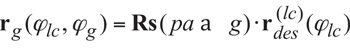
When the gears rotate, the desired line of contact, LCdes travels with respect to a reference system XgYgZg associated with the gear. Simultaneously, LCdes travels with respect to a reference system XpYpZp associated with the pinion. Therefore, the gear tooth flank, G, can be viewed as a loci of consecutive positions of the line of contact, LCdes, in the reference system XgYgZg . Similarly, the pinion tooth flank, P, can be viewed as a loci of consecutive positions of the line of contact, LCdes, in the reference system XpYpZp. To derive equations for the position vectors of a point of the gear tooth flank, rg, and the pinion tooth flank, rp, the operators, Rs (pa→g) and Rs (pa→p), of transition from the reference system XpaYpaZpa to the reference systems XgYgZg and XpYpZp are used:
(Equation 4)
(Equation 5)
The operator of the resultant coordinate system transformation Rs (pa→g) is a function of the angle of rotation of the gear, Φg, and of the angular parameter, Φlc. The operator of the resultant coordinate system transformation Rs (pa→p) is a function of the angle of rotation of the pinion, Φp, and of the angular parameter Φlc.
The position vectors, rg and rp, are expressed in terms of Gaussian parameters Φlc and Φg of the gear tooth flank, G, and Gaussian parameters Φlc and Φp of the pinion tooth flank, P, correspondingly.
The operator Rs (pa→g) of the resultant coordinate system transformation can be represented in the form of the product of the operators of the rotations in [6]:
 (Equation 6)
The operators of the rotations ![]() ,
, ![]() ,
, ![]() , and
, and ![]() are the standard operators of the linear transformations. For the calculation of the operators, standard formulae [1] can be used. Similarly, the operator
are the standard operators of the linear transformations. For the calculation of the operators, standard formulae [1] can be used. Similarly, the operator ![]() of the resultant coordinate system transformation can be represented in the form of the product of the operators of the rotations:
of the resultant coordinate system transformation can be represented in the form of the product of the operators of the rotations:
(Equation 7)
The operators of the rotations ![]() and
and ![]() are also the standard operators of the linear transformations. For the calculation of the operators, standard formulae [1] can be used.
are also the standard operators of the linear transformations. For the calculation of the operators, standard formulae [1] can be used.
The developed mathematical models of the tooth flanks G and P can be used for the development of the CAD models of the gear and the pinion. Later on the CAD models are necessary for the manufacturing purposes of the gear and the pinion, that is, the CAD model can be converted to the corresponding G-code for a 5-axis NC machine for cutting the prototype gears. Another purpose of the CAD models is a more detailed investigation of the gearing by means of special FEA computer means.
Additional Authors:
Vishnu Irigireddy, MS,Apex Tool Group, LLC, Lexington, South Carolina, USA. Phone: +803-808-6738 (off), 803-466-1087 (cell), e-mail: vishnu.irigireddy@apextoolgroup.com. Sandeep M. Vijayakar, Ph.D., advanced Numerical Solutions LLC. 3962 Brown Park Drive, Suite C, Hilliard OH 43026 USA, Phone: (614)771-4861 (614)771-4861, Fax: (614)453-8762, e-mail: sandeep@ansol.com. John Stewart, Apex Tool Group, LLC, Lexington, South Carolina, USA, Phone: +803-951-7559 (off), 803-800-4547 (cell), e-mail: John.Stewart@apextoolgroup.com. Ty P. Warner, P.E., TYKA Engineering, LLC, Eagle River, Wisconsin, USA, Phone: +218-341-9689 (cell), e-mail: tywarner@peoplepc.com


