


Abstract
This paper is aimed at the development of a novel design of precision gear hob for the machining of involute gears on a conventional gear-hobbing machine. The reported research is based on the use of fundamental results obtained in analytical mechanics of gearing. For solving the problem, both the descriptive-geometry-based methods (further DGB-methods) together with pure analytical methods have been employed. The use of DGB-methods is insightful for solving most of the principal problems, which consequently have an analytical solution. These analytical methods provide an example of the application of the DG/K-method of surface generation earlier developed by the author. For interpretation of the results of research, several computer codes in the commercial software MathCAD/Scientific were composed. Ultimately, a method of computation of parameters of design of a hob with straight-line lateral cutting edges for the machining of precision involute gears is developed in the paper. The coincidence of the straight-line lateral cutting edges of the hob with the straight-line characteristics of its generating surface eliminates the major source of deviations of the hobbed involute gears. The relationship between major principal design parameters that affect the gear hob performance are investigated with use of vector algebra, matrix calculus, and elements of differential geometry. Gear hobs of the proposed design yield elimination of the principal and major source of deviation of the desired hob tooth profile from the actual hob tooth profile. The reported results of research are ready to put in practice. Part I is presented here, with the conclusion to appear in the May issue of the magazine.
 Introduction
Gear hobs are recognized as economical cutting tools for the machining of spur and helical gears. Almost any external tooth form that is uniformly spaced about a center can be hobbed. Application of gear hobs of special design yields machining of internal gears as well. In order to achieve high accuracy of hobbed gears, lateral cutting edges of an involute gear hob are required to be located on the surface of involute worm. It is also required that this worm is in proper mesh with the involute gear to be machined. Usually this worm is referred to as the generating (machining) surface of an involute hob [1]. Lateral cutting edges of the hob teeth align with the line of intersection of the generating surface of a gear hob by rake face of the hob tooth. These lines are curved lines. For the manufacturing purposes, the required curved lateral cutting edges of the involute hob teeth usually are approximated with the straight-line lateral cutting edges. Approximation of that kind results in deviations of the actual lateral cutting edges of the involute hob from the generating surface of the hob. The deviations of that kind are the major source of the gear tooth deviations, and are unavoidable for gear hobs of conventional design.
Analysis of known designs of involute hobs [2], [3] and others reveals that no design of a hob with straight-line lateral cutting edges are developed yet for he machining of precision involute gears.
Formulating the problem at hand: To develop a method for computation of parameters of a novel design of gear hob with straight-line lateral cutting edges for the machining of precision involute gears.
The method of computation of parameters of design of a hob with straight-line lateral cutting edges for machining of precision involute gears is reported in the paper.
Outline: The paper is organized in the following way. In Section 2 generation and geometry of the generating (machining) surface on the involute hob is investigated. For this purpose, equation of the gear screw involute tooth surface is utilized. Ultimately the generating surface of the involute hob is determined in both ways; say, using the DGB-approach, and analytically as well. Use of the DGB-approach is insightful for derivation of equations for computation of major design parameters of the gear hob. The concept of design of the precision involute gear hob with straight-line lateral cutting edges, as well as computation of principal parameters of its design, is considered in Section 3. A practical example of computation of parameters of design of the precision involute hob of proposed design is considered. In Section 4 a possible enhancement of the developed theory to the area of hobbing of involute gear with modified tooth profile is reported. This consideration is based largely on application of the DG/K-approach1 of surface generation earlier developed by the author. Part II ends with Conclusions and Acknowledgement.
2: The Generation Surface T on an Involute Hob
Determination of the generation surface of a cutting tool is the start point for designing the tool. We refer to the generation (i.e. to the machining) surface of a cutting tool as to a surface that is conjugate to the surface being machined [1], [6]. Concerning a gear hobbing operation, the generating surface T of an involute hob is represented by a screw involute surface that is conjugate to the gear tooth surface being machined. Parameters of shape of the surface T can be expressed in terms of (a) parameters of shape of the gear tooth surface G, and (b) parameters of relative motion of the hob with respect to the gear.
Several methods for generation of the surface T of a cutting tool are known [1]. Following common practice, for generation of the surface T of an involute gear hob the single-parametric method can be used [1]. This method is based on the first method of generation of enveloping surfaces proposed by Olivier2 [7].
The generating surface T of a gear hob could be generated in three steps. For this purpose it is required (a) to specify the gear tooth surface to be machined, (b) to generate an auxiliary phantom rack R , and, finally (c) to generate the surface T itself. Below, the generating surface T of an involute gear hob is determined following the above listed routine.
2.1.
Gear tooth surface. Gear tooth surface G is a screw involute surface. In the left-handed Cartesian coordinate system XgYgZg it can be described analytically in terms of curvilinear (Gaussian) parameters Ug and Vg [8]
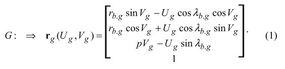
Here, in Eq. (1) is designated
rb.g = the gear base radius (rb.g = 0.5db.g=, and db.g is the gear base diameter)
λg.b = base lead angle
p = screw parameter of the gear tooth surface G
The interested reader may wish to go to [1], [8] for details on Eq. (1).
Equation (1) of the gear tooth surface G is of critical importance for the analysis following below. Mostly, this is because it is helpful for derivation of equation of the auxiliary phantom rack R , and of the generating surface T of the involute hob.
2.2.
The auxiliary phantom rack R . The auxiliary phantom rack R of an involute gear hob can be generated as an enveloping surface to consecutive positions of the gear tooth surface G in its motion relative to the coordinate system XR YRZR associated with the rack R . For generation of the auxiliary rack R , the left-handed Cartesian coordinate system XRYRZR has been employed. Generation of the auxiliary rack R is illustrated in Figure 1.

The gear being machined is rotating about it axis Og with a certain angular velocity ωg. A pitch plane WR of the rack R is moving straightforward. Velocity of this translational motion is designated as VR . The rotation ωg and the translation VR are synchronized in a timely manner. This results in that the pitch plane WR is rolling without sliding over the pitch cylinder of diameter Dg of the gear. Without going into details, one can come up with the conclusion that the lateral surfaces of the auxiliary rack R teeth are the planes. Face-width FR of the rack R is identical to the face-width Fg of the gear (ψg≡ψR). Pitch helix angle ψR is identical to the pitch helix angle ψg of the gear (Fg≡FR). The auxiliary rack R makes contact with the gear tooth surface G along straight-line segment AB, which is often referred to as the characteristic Eg.
The intuitive understanding of the shape of the lateral tooth surfaces of the rack R is helpful but not sufficient. For further consideration, equation of the rack R tooth surface is required to be derived.The major coordinate systems to be used in this research are the following: (a) the coordinate system XgYgZg embedded to the gear, (b) the coordinate system XRYRZR associated with the auxiliary rack R (%%0407ASMEfig2.jpg%%), and ultimately XhYhZh connected to the involute hob. A few more intermediate coordinate systems were used as well.
The auxiliary rack tooth surface R could be represented as an enveloping surface to consecutive positions of the gear tooth surface G, while the pitch plane WR is rolling without sliding over the pitch cylinder of diameter Dg. This concept can be used for derivation of equation of the surface R.
In order to derive equation of the surface R, it is necessary to represent (a) the gear tooth surface G, (b) the pitch plane WR , and (c) their relative motion in a common coordinate system XR YR ZR . Therefore, the operator Rs(g0 R 1) of the resultant coordinate system transformations is required to be composed.

The resultant coordinate system transformation could be analytically represented as a superposition of several elementary coordinate system transformations (Figure 2). The elementary coordinate system transformations could be analytically described by (a) the operator Rt(φ,Zg) of rotation about Zg axis through an angle φ,(b) the operator Tr(−0.5Dg,YR ) of translation along YR axis at a distance −0.5Dg, and (c) the operator Tr(−l,XR) of translation along XR axis at a distance −l . The considered operators of the elementary coordinate system transformations yield equation for Rs(g0 R 1)

The interested reader may wish to go to [1] [9] for details of coordinate system transformations.
Angle φ can be computed from equation φ = ωgt, and length l=| VΣ|⋅t, where t designates time. Therefore, the gear tooth surface Gt in its current location in the coordinate system XR YR ZR could be analytically described by equation
![]()
Equation (3) for Gt can be cast into the form rg.t (Ug,Vg,t), which is expressed in term of the parameter t of relative motion. This immediately yields analytical representation for the lateral tooth surface of the auxiliary rack R
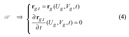
Exploding Eq. (4) and eliminating the enveloping parameter t, one can come up with an equation of the lateral tooth surface of the auxiliary rack R in matrix representation.
Equation (5) for R could also be derived using equation of contact ng⋅VΣ.g= 0 [1], [4]. Here ng designates the unit normal vector to the surface G , and VΣ.g designates velocity vector of relative motion of the surface G and of a coordinate system embedded to the auxiliary rack R . Unit normal vector ng could be computed from the equation ng =ug x vg, where ug =Ug |Ug|, vg =Vg |Vg|, and Ug =∂rg∂Ug, Vg =∂rg ∂Vg. Relative motion of the gear G and of the auxiliary rack R yields representation in the form of instant rotation about pitch point P . Therefore,vector VΣ.g could be represented as the vector of linear velocity of instant rotation about P.
The actual value of the auxiliary rack normal pressure angle φR is equal to the gear normal pressure angle at the pitch point when it meshes with the rack R . Variation of kinematics of relation motion results in corresponding variation of normal pressure angle φR (see [10] for details). In a gear hobbing operation, use of hobs with different normal pressure angle causes transition curves of different parameters (see [10] for details).
2.3.
The generating surface T of an involute hob. The surface T of an involute hob can be generated as enveloping surface to consecutive positions of the auxiliary phantom rack R in its screw motion relative to the hob axis. In order to get a comprehensive understanding of the involute hob geometry, it is helpful to consider two different approaches for determining of the surface T . The first approach is a descriptive-geometry-based approach to which we refer to as the DGB-approach3. The second approach is an analytical one. It is usually referred to as the DG/K-approach4. The DGBapproach gives a fruitful insight to the development of the DG/K-approach. It could be considered as a perfect “filter” for the elimination of rough errors of the analysis. Both the approaches complement one another, and together they provide the user with profound understanding of the involute hob geometry and kinematics of the surface T generation [8], [11], [12].
2.3.1.
The DGB-approach of the surface T generation. It is convenient to subdivide the problem of generation of the gear hob surface T onto several sub-problems.
Base helix angle. For solving of the problem of determining of the hob base helix angle, actual values of normal pressure angle φn and the hob-setting angel ζh are required been known.
The solution to the problem under consideration is represented in the system of three planes of projections. They are π1, π2 and π3 respectively. An auxiliary plane of projections π4 is also used.
In order to determine the hob base helix angle ψb.h using DG-based method, the lateral tooth surface of the auxiliary rack R is required been constructed. Let’s start from an arbitrary plane A that is orthogonal to the axis of projections π1 π2 (Figure 3). The plane A is specified by the traces A1 and A2 . After being turned about the trace A2 through the hob-setting angle ζ h the plane A occupies the position of the plane Q . The plane Q is specified by the traces Q1 and Q2 . Then the plane Q is turned about the trace Q1 through the normal pressure angle φn of the hob tooth. In this final location, the plane is designated as R , and it is specified by the traces R1 and R2 respectively.

In order to construct the hob base helix angle ψb.h in this particular configuration (location and orientation) of the plane R , an auxiliary plane of projections π4 is constructed. The axis π1/π4 is orthogonal to the trace R1.
The hob base helix angle ψb.h is the angle that the lateral rack surface R makes with a plane that (a) is orthogonal to the horizontal plane of projections π1 , and (b) is orthogonal to the trace R 4. Use of conventional descriptive geometry rules yields construction of the hob base helix angle ψb.h, as well as the hob base lead angle λb.h that complements the angle ψb.h to 90? (Figure 3).
The derived solution (Figure 3) to the sub-problem of determining of the base helix angle ψb.h gives an insight to how an expression for computation of ψb.h can be derived. Using the above solution (Fig. 3), one can come up with the equation [1], [13], [14].
![]()
Equation (6) could also be represented in the form
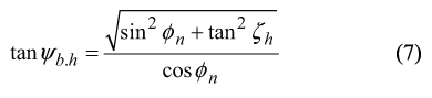
Here is designated
φn = normal pressure angle
ζh = hob-setting angle
Base lead angle λ b.h can be computed from the equation λ b.h =90?−ψb.h
Base diameter of an involute hob. The generating surface T of a gear hob can be represented as an enveloping surface to consecutive positions of the plane R that is performing a screw motion around the hob axis of rotation.

Consider the plane R in a system of planes of projections π1π2π3 (Figure 4). The plane R is performing a translational motion along the axis π1/π2 with a certain velocity VR . Simultaneously, the plane R is rotating about that same axis π1/π2 with an angular velocity ωR .
The base diameter db.h of the involute hob is equal to the shortest distance of approach between the characteristic E and the axis π1/π2. In order to determine the characteristic E it is required to select those points of the plane R at which the resultant speed of the plane points is perpendicular to the normal vector NR to the plane R itself. For this purpose, velocity of translational motion VR is required to be considered together with linear velocity of rotation ωR . Those points of the plane R at which the resultant velocity VΣ is orthogonal to NR belong to the characteristic E . The characteristic E is the straight-line at a distance 0.5⋅ db.h from the hob axis of rotation that crosses the axis at the base helix angle ψb.h of the hob.
The solution to the problem of determining the base diameter db.h is depicted in Figure 4 The developed solution to the sub-problem under consideration is insightful for derivation of the equation
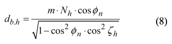
for computation of the diameter db.h .
Here is designated
m = hob modulus
Nh = number of starts of the hob
2.3.2.
The DG/K-approach of generation of the surface T of an involute hob. Equation of the generating surface T of an involute gear hob can be derived using elements of theory of enveloping surfaces, which is a part of DG/K-approach of surface generating.
In order to derive equation of the surface T , it is convenient to consider the relative motion that the auxiliary rack R is performing with respect to the coordinate system XhYhZh embedded to the hob. The coordinate system XhYhZh is the left-handed Cartesian coordinate system (Figure 5).

Similarly to Eq. (2), the operator Rs(R ![]() T) of the resultant coordinate system transformation could be composed
T) of the resultant coordinate system transformation could be composed
![]()
In Eq. (9), the hob angle of rotation is equal to ψ =| ωh | ⋅t , and translation of the auxiliary rack R can be computed from the equation l =|VR |⋅t. The hob pitch diameter is designated as dh .
The derived Eq. (5) together with Eq. (9) could be employed for analytical description of the auxiliary rack R that is performing a screw motion with respect to the hob axis of rotation Oh. Corresponding equation for the auxiliary rack Rt in its arbitrary position is as follows.

The generating surface T of the involute gear hob can be analytically described by the set of two equations
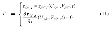
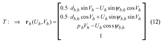
After substituting of Eq. (4), the Eq. (11) casts into
For computation of the hob base diameter db.h and the hob base helix angle ψb.h Eq. (6) and Eq. (8) can be employed.
Equation (12) is of critical importance for the development of a novel design or gear hob for hobbing of precision involute gears. Important features of geometry of the surface T are the major reasons for this. It is easy to verify that for a specific value of Vh , Eq. (12) describes a straight-line on T , the so-called the characteristic line Et . Further, the lateral cutting edge of the involute hob will be aligned with the straight-line characteristic Et . Therefore, the straight-line characteristic Et will serve as a vital link between the geometry of the generating surface T of the involute hob and the principal features of its design. Again, this intermediate result is of critical importance for the analysis that follows.
Equation (12) for the surface T could also be derived using equation of contact nR ⋅VΣ.R =0 [1], [4]. Here nR designates the unit normal vector to the surface R , and VΣ.R designates velocity vector of relative motion of the surface R and of the coordinate system XhYhZh embedded to the hob. The unit normal vector nR could be computed from equation nR =uR × vR , where uR =∂UR /|∂UR |, vR =∂VR/|∂VR|, and UR = ∂rR /∂UR , VR = ∂rR /∂VR. It is convenient to decompose VΣ.R onto VΣ.R =V(n)R +V(t)R . Motion with V(n)R is directed perpendicular to the auxiliary rack R . This motion results in enveloping surface T . Motion with V(t)R is directed along the auxiliary rack R. This motion results in sliding of the auxiliary rack surface R over itself. It doesn’t affect the shape of the surface T and, therefore, it is out of our current interest. Ultimately, the decomposition of VΣ.R yields elimination of V(t)R , and simplifies further analysis.
3: Principal Parameters of Design of the Involute Gear Hob
The above consideration (see sub-section 2.3) yields a conclusion, which is significant for further development of an involute gear hob of the novel design. The concept of the novel design of an involute hob is based on the following considerations: (a) lateral cutting edges of one side of an involute hob tooth belong to the corresponding screw involute surface; (b) lateral cutting edges of the opposite side of the involute hob tooth belong to the opposite screw involute surface; (c) the screw involute surfaces of the opposite sides of the involute hob tooth intersect each other, and the line of intersection is a helix; (d) two characteristics El and Er are passing through every point of the helix; (e) the two characteristics El and Er through the common point of the helix intersect one another at that point and, thus they specify a plane; (f) that plane is used as a rake-face of the involute hob teeth.
The above listed steps yield determination of orientation of the rake-face of the involute hob teeth.
3.1.
The DGB-approach of determining of orientation of the rake-face. The DGB-solution to the problem of determining of orientation of the rake-face of the involute hob teeth is depicted in Figure 6.

For solving of the problem of determining of orientation of the hob tooth rake-face, the following parameters of design of the hob are required to be known: the hob tooth modulus m , normal pressure angle φn , the hob-setting angel ζ h , number of starts of the hob N h , the hob outside diameter Do.h , and the hob base diameter db.h .
The solution to the problem under consideration is represented in the system of three planes of projections π1, π2 and π3 respectively. Two auxiliary planes of projections, say π4 and π5, are also used. The auxiliary axis of projections π1/π4 makes the hob-setting angle ζ h with the axis of projections π1/π2. The axis of projections π1/π5 is parallel to the axis π1/π4. Use of the plane of projections π5 yields considerable size reduction of Figure 6.
In the system of three planes of projections π1, π2 and π3 , the axis of the hob rotation O is oriented parallel to the axis π1/π2 (Figure 6).
Normal plane section of the auxiliary rack R tooth is shown in the plane of projections π4 .
Consideration of images of the hob elements in the planes of projections π4 and π3 (that are connected to one another through the planes of projections π1 and π2) yields determination of location of the point A within π3 . Two straight lines through A3 that are tangent from the opposite sides to the hob base cylinder of diameter db.h represent straight lines which the lateral cutting edges of the hob align to. The rake-plane of the hob tooth is the plane through these two straight lines. Conventional methods of descriptive geometry are used for the construction of all others projections of these two straight lines that initially are constructed in π3 .
Angle ξ that the rake-plane makes with the hob axis of rotation O is constructed in the plane of projections π1.
The hob tooth profile in the rake-plane is shown in the plane of projections π5 .
3.2.
The DG/K-approach of determining of orientation of the rake-face. Figure 6 provides a clear understanding of the geometry of the precision involute gear hob with straight-line lateral cutting edges. Understanding features of the hob geometry (see sub-section 3.1) is very helpful for derivation of equations for computation of major parameters of the gear hob of the developed design.
3.2.1.
An auxiliary parameter R . Lateral tooth surfaces of the auxiliary rack R intersect each other along a straight line through the point A (Figure 7). This straight line is at a distance R from the hob axis. For the distance R Figure 8 yields
![]()


3.2.2.
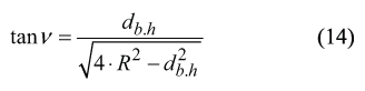
The angle φr between the lateral cutting edges of the hob tooth. Prior to deriving the equation for computation of the angle φr that make the lateral cutting edges of the gear hob tooth, it is convenient to derive an equation for computation of projection ν of the angle φr onto the coordinate plane XhYh.
The projections of the lateral cutting edges of the involute tooth onto the coordinate plane XhYh make an angle ν.
For computation of the actual value of the angle ν , the following expression can be used
Then, consider three unity vectors A, B, and C. These vectors yield the following analytical representation
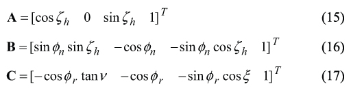
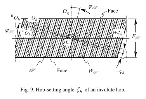
Here ζ h designates the hob-setting angle of the involute hob. The angle ζh is measured in the auxiliary rack R pitch plane. It is the angle that makes a perpendicular to the rack R tooth and axis of rotation of the hob (Figure 9) [8],[14]

Required for further computations, the hob-setting angle ζh can be chosen by a designer of the gear hob. Usually it is recommended to assign the actual value of the hob-setting angle ζh equal to the pitch helix angle ψh of the hob. As it is proven in our earlier work [14], in order to satisfy the equality ζh=ψh (this condition is the best possible) the actual value of the hob-setting angle is required to be computed from the equation.
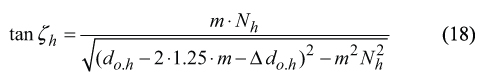
Here Δ do.h designates reduction of the hob outside diameter do.h due to re-sharpening of the worn gear hob (Fig. 10). Figure 10 yields very simple formula for computation of Δdo.h = (do.h(new) −do.h(worn)).

The idea of the hob-setting angle can be traced back to the publication by Buckingham (1963) [11].
As the vectors A , B , and C are located within the common lateral surface of the auxiliary rack R , therefore the following identity A×B⋅C≡ 0 observes. The last expression yields a determinant
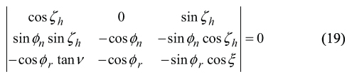
After exploding of the determinant, and after the necessary formulae transformations are performed, one can come up with the equation of two unknowns, namely of φr and ξ .
3.2.3.
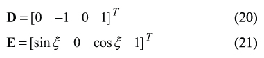
The angle ξ of intersection of the rake-face and of the hob axis of rotation. Rake-face of the involute hob is inclined to the hob axis at a certain angle ξ . In order to determine the required value of the angle ξ , the following three unity vectors C, D, and E were used. For the vectors D and E Figure 8 yields
As of the vectors C, D, and E are located within the rake-face of the hob tooth, therefore the following identity C×D⋅E≡ 0 observes. This yields a determinant
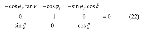
After exploding of the determinant, and after the necessary formula transformations are performed, one can come up with the one more equation of two unknowns, namely of φr and ξ .
Further, consider the set of two equations, say of Eq. (19) and Eq. (22) of the two unknowns φr and ξ . Solution to the set of the above equations can be represented in the form
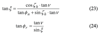
The hob-setting angle ζh specifies inclination of the gear hob axis of rotation Oh with respect to the auxiliary rack R . It is necessary to point out here that the angle ζh is a parameter of the gear hob design, and is not a parameter of gear hobbing operation. Figure 9 reveals that it could be either positive ( +ζh > 0o ), or negative (−ζh< 0o.), as well as it could be of zero value (ζh= 0o. Under special conditions, the hob-setting angle could be equal to the gear hob pitch helix angle ψR (i.e. the equality ζh=ψR could be observed).
The above Eq. (23) and Eq. (24) are necessary for computation of the required values of the angles φr and ξ. These angles are necessary been indicated in the involute hob blueprint.
The involute hob of novel design [15] with the angle ξ computed from the Eq. (23), and the angle φr computed from the Eq. (24) (a) has straight-line lateral cutting edges, and (b) it is free of the major source of the tooth profile deviations. Two more modifications of the gear hob design [16], [17] are developed as well.
Example of computation. The above derived equations yield computation of parameters of the novel hob design for machining of precision involute gears. Such computations can be done, for example, for the single-start FETTE gear hob (DIN 8002A, Cat.-No 2022, Ident. No 1202055) of module m =10 mm , outside diameter do.h = 180mm, and pressure angle φn = 20o [18].
Results of computation are collected in the Table 1.

References
- Radzevich, S.P., Fundamentals of Surface Generation. Monograph, Kiev, Rastan, 2001, 592p. – Copy of the monograph is available from The Library of Congress.
- Bregi, B.F., Erxleben, R.F., Tersch, R.W., et al, Modern Methods of Gear Manufacture, 4th Edition, National Broach & Machine Division/Lear Siegler, Inc., 5600 St. Jean Ave., Detroit, MI 48213, 1972, 160p.
- Townsend, D.P., Dudley’s Gear Handbook. The Design, Manufacture, and Application of Gears, 2nd Edition, McGraw Hill, Inc., New York, 1991.
- Radzevich, S.P., Sculptured Surface Machining on Multi-Axis NC Machine, Monograph, Kiev, Vishcha Shkola Publishing House, 1991, 192p. – Copy of the monograph is available from The Library of Congress.
- Radzevich, S.P., “Diagonal Shaving of an Involute Pinion: Optimization of Parameters of the Pinion Finishing Operation”, The International Journal of Advanced Manufacturing Technology. (In press).
- Radzevich, S.P., “Conditions of Proper Sculptured Surface Machining”, Computer-Aided Design, Vol.34, No 10, September 2002, pp.727-740.
- Olivier, T., Theorie Geometrique des Engrenages, Paris, 1842.
- Radzevich, S.P., “About Hob Idle Distance in Gear Hobbing Operation”, ASME J. of Mechanical Design, December, 2002, Vol. 124, Issue 4, pp.772-786.
- Radzevich, S.P., “Design of Shaving Cutter for Plunge Shaving a Topologically Modified Involute Pinion”, ASME J. of Mechanical Design, September 2003, Vol. 125, Issue 3, pp.632-639.
- Radzevich, S.P., “A Novel Approach for Computation of Constraints on Parameters of Modification of the Tooth Addendum of Precision Involute Hob”, ASME J. of Mechanical Design, July 2006, Vol. 128, Issue 6, pp.000-000.
- Buckingham, E., Analytical Mechanics of Gears, Dover Publications, Inc., New York, 1963, 546p. [12] Radzevich, S.P., “A Descriptive-Geometry-Based-Solution to a Geometrical Problem in Rotary Shaving of Shoulder Pinion”, ASME J. of Manufacturing Science and Engineering, November, 2005, Vol. 127, Issue 4, pp. 893-900.
- Radzevich, S.P., Design and Investigation of Skiving Hobs for Finishing Hardened Gears, Ph.D. Thesis, Kiev Polytechnic Institute, 1982, 286p.
- Radzevich, S.P., Cutting Tools for Machining Hardened Gears, Moscow, VNIITEMR, 1992, 60p.
- Pat. No. 990.445 (USSR), A Precision Involute Hob./S.P. Radzevich, Filed: October 08, 1981, Int. Cl. B23F 21/16.
- Pat. No. 1.114.505 (USSR), A Precision Involute Hob./S.P. Radzevich, Filed: October 18, 1982, Int. Cl. B23F 21/16.
- Pat. No. 2.040.376 (Russia), A Precision Involute Hob./S.P. Radzevich et al, Filed: January 03, 1992, Int. Cl. B23F 21/16.
- FETTE. Gear Cutting Tools: Hobbing, Gear Milling, Leitz Metalworking Technology Group, 196p.
Foot Notes
1) The DG/K-approach is based on fundamental results obtained in differential geometry of surfaces, and in kinematics of multi-parametric motion of a rigid body in E3 space (For details see (i) Radzevich, S.P., Sculptured Surface Machining on Multi-Axis NC Machine. Monograph, Kiev, Vishcha Shkola Publishers, 1991, 192p – Copy of the monograph is available from The Library of Congress [4]; and (ii) Radzevich, S.P., Fundamentals of Surface Generation. Monograph, Kiev, Rastan, 2001, 592p – Copy of the monograph is available from The Library of Congress [1]). A perfect example of application of the DG/K-approach is disclosed in the paper: Radzevich, S.P., “Diagonal Shaving of an Involute Pinion: Optimization of Parameters of the Pinion Finishing Operation”, The International Journal of Advanced Manufacturing Technology. (In press) [5].
2) Olivier, T. disclosed two principal methods of generation of enveloping surfaces in his work published as early as in
3) The DGB-approach proved to be useful for solving variety of gear related problems (see, for example, the monograph by Buckingham [11], as well as more recent publications [8] [12]).
4) The DG/K-approach is based on fundamental results obtained in differential geometry of surfaces, and in kinematics of multi-parametric motion of a rigid body in E3 space. The method is disclosed in two monographs [1], [4] by the author. Both the monographs are available form the Library of Congress.


